1 Polymer electrolytic capacitor —The proposal of highly conductive polymer electrolytic capacitor
The biggest problem of electrolytic capacitors has always been the large ESR. Although aluminum electrolytic capacitors already have low ESR types, which can significantly reduce the ESR, there is still no qualitative change. ESR is caused by the negative electrode resistance of the electrolytic capacitor. The conductivity of the negative electrode material of conventional (including low ESR) aluminum electrolytic capacitors is relatively low (3ms/cm). The performance of the electrolytic capacitor will not be qualitatively improved without changing the negative electrode material. One of the methods to improve the conductivity of the negative electrode is to use manganese dioxide whose conductivity is close to the negative electrolyte of the aluminum electrolytic capacitor. The conductivity can reach 30mS/cm. At the same time, the anode material should also be changed to metallic tantalum, and the insulating medium should be changed to five. Tantalum oxide, tantalum electrolytic capacitor. The emergence of tantalum electrolytic capacitors has greatly reduced the ESR of electrolytic capacitors, but it is relatively expensive and has limited rated voltage (less than 63V), so film capacitors are often used in many applications (singles can easily reach 40μF/75V and 80μF/ 30V) or ceramic laminated capacitors (single units have reached 200μF/6.3V) instead of electrolytic capacitors to achieve filtering of switching power supplies and power modules. As we all know, the capacitance of film capacitors and ceramic laminated capacitors is far inferior to electrolytic capacitors, and their application is inconvenient. How to further improve the conductivity of the negative electrode material of the electrolytic capacitor is a good way to improve the performance of the electrolytic capacitor and even the performance of the capacitor. In the context of this application demand, the negative electrode of the organic polymer of the solid aluminum electrolytic capacitor can make the conductivity reach 1000mS/ cm is even 10000mS/cm, so the ESR of the electrolytic capacitor made of negative electrode material will be very low! The conductivity of various negative electrode materials of electrolytic capacitors is shown in Figure 1-1.
Figure 1-1 Conductivity of various negative electrode materials of electrolytic capacitors
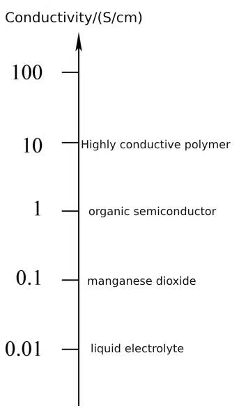
Figure 1-1 Conductivity of various negative electrode materials of electrolytic capacitors
The structure of the solid aluminum electrolytic capacitor is the same as that of the ordinary aluminum electrolytic capacitor. The difference is that the negative electrode material of the solid aluminum electrolytic capacitor uses a polymer conductive polymer instead of the electrolyte, so that the negative electrode changes from liquid to solid. In addition to leaded solid electrolytic capacitors, laminated solid electrolytic capacitors have also appeared. The structure of the laminated solid aluminum polymer electrolytic capacitor is a unique structure that combines the characteristics of aluminum electrolytic capacitors and tantalum electrolytic capacitors. Like traditional aluminum electrolytic capacitors, the aluminum oxide layer of the positive aluminum foil of the laminated solid aluminum polymer electrolytic capacitor is formed on the positive aluminum foil through a chemical formation process. In the laminated solid aluminum polymer electrolytic capacitor, a highly conductive polymer film is deposited on alumina as the negative electrode, and graphite and silver are used to lead out the solid polymer negative electrode. This is similar to the solid tantalum electrolytic capacitor which uses graphite to combine manganese dioxide. The negative lead is similar.
2 Polymer electrolytic capacitor —a brief description of the manufacturing process of highly conductive polymer solid electrolytic capacitors
The manufacturing process of highly conductive polymer solid electrolytic capacitors mainly includes nailing, carbonization, formation, polymer injection, polymerization, assembly, testing, etc.
The manufacturing process before nailing and coiling is the same as that of liquid electrolytic capacitors. Different from liquid electrolytic capacitors, the rolled capacitor core also requires a “carbonization” process, because in solid electrolytic capacitors, the capacitor paper is useless and is not conducive to the good bonding between the polymer and the positive and negative electrode foils. Electrical contact, so it needs to be ablated or carbonized. This process uses high temperature to carbonize the capacitor paper.
After carbonization, the capacitor core enters the formation process. The formation process is a repair process of damage to the aluminum oxide film of the positive electrode foil caused by all previous manufacturing processes (such as slitting, riveting during the nailing and rolling process of the nailing and rolling machine, etc.), which is similar to the normal temperature aging and high temperature aging processes of liquid electrolytic capacitors. This process needs to be completed before the polymer is injected into the core. Once the polymer is injected into the core, the aluminum oxide film of the positive electrode foil cannot be repaired, eventually causing the solid electrolytic capacitor to be scrapped.
The formation process is to immerse the carbonized core in the formation liquid at a certain temperature of the formation liquid. The formation liquid is the negative electrode, so you only need to apply the positive voltage required for formation to the positive electrode pin of the core until all the damaged parts of the aluminum oxide film of the positive electrode foil are repaired and the formation process is completed.
After formation, the polymer injection process begins. There are two methods of polymer injection: injecting the original material of the polymer into the capacitor core, and completing the polymerization of the polymer in the capacitor core; completing polymerization outside the capacitor core, and then injecting it into the capacitor core. The former is a manufacturing process for low-voltage solid electrolytic capacitors, and the latter is mostly a manufacturing process for high-voltage solid electrolytic capacitors.
Polymers injected into the capacitor core and then polymerized are not suitable for high-voltage solid electrolytic capacitors. The main reason is that the aluminum oxide film of the positive electrode foil of high-voltage solid electrolytic capacitors is relatively thick. The thicker the aluminum oxide film, the more fragile it is and can easily break under the action of external forces, resulting in A short circuit in the solid electrolytic capacitor, or even the stress release process after the solid electrolytic capacitor is subjected to slight vibration or polymerization, can cause the aluminum oxide film of the positive electrode foil to break and short circuit between the positive and negative electrodes.
For low-voltage solid electrolytic capacitors, the aluminum oxide film of the positive electrode foil is very thin and can withstand a certain degree of external force. After the polymer is injected into the core, polymerization can achieve lower ESR, which is important for low-voltage solid electrolytic capacitors.
After the polymer is injected into the core, it enters the polymerization process, which is similar to the curing process of epoxy resin and uses high-temperature polymerization.
The polymer is polymerized outside the capacitor core and then injected into the capacitor core. This process is to polymerize the polymer and break it into a size that can be injected into the capacitor core. Through solvent carrying, the solvent with polymer is impregnated into the capacitor core, and then the solvent is evaporated from the core. Since the amount of polymer that can be loaded into the capacitor core at one time cannot reach the required amount, the capacitance and ESR cannot reach the design values, and it is necessary to repeatedly impregnate the core with the solvent containing the polymer. , then evaporate the solvent and leave the polymer in the capacitor core until the capacitance and ESR reach the design specifications. Relatively speaking, the more times this process is repeated, the better the performance of the capacitor, but the manufacturing cost increases significantly and the manufacturing process takes longer. Comprehensive considerations are needed to adopt the best compromise manufacturing process.
After the solid electrolytic capacitor completes the polymerization process, it actually has all the electrical parameters of the solid electrolytic capacitor. The next step is to install it in the shell, that is, assembly. The assembly process is the same as that of liquid electrolytic capacitors and will not be described again.
After assembly, the solid electrolytic capacitor passes the test and the performance parameters meet the requirements, it is a qualified product and is usually called a good product.
The above is an analysis of the manufacturing process of polymer electrolytic capacitor.
3 Polymer electrolytic capacitor – general electrical parameters of solid electrolytic capacitors
Like other capacitors, the voltage parameter of solid electrolytic capacitors is one of its important parameters. The voltage parameters of solid electrolytic capacitors mainly include formation voltage, rated voltage, etc.
3.1 Polymer electrolytic capacitor –voltage
3.1.1 Formation voltage Formation voltage is divided into positive electrode foil formation voltage and solid electrolytic capacitor core formation voltage.
The positive foil formation voltage is provided by the formation foil manufacturer. This voltage should be higher than the formation voltage of the solid electrolytic capacitor core.
Figure 1-2 shows the relationship between the operating voltage and temperature of a tantalum electrolytic capacitor.
In Figure 1-2, at 85°C, tantalum electrolytic capacitors can operate at rated voltage. As the temperature exceeds 85°C, the actual operating voltage of tantalum electrolytic capacitors decreases at a rate of 8% to 10% per 10°C. 150°C , the actual operating voltage drops to half of the rated voltage.
From the operating voltage and temperature characteristics of tantalum electrolytic capacitors and the temperature characteristics of aluminum electrolytic capacitor foils, it can be inferred that the relationship between the rated voltage of solid aluminum electrolytic capacitors at the highest temperature and the core formation voltage of 70°C is that the formation temperature is 70°C, and the corresponding formation The voltage needs to be about twice the rated voltage corresponding to 125°C!
This conclusion can also be drawn from the solid electrolytic capacitor data. Figure 1-3 shows the relationship between the temperature and the external voltage that can be applied to a solid electrolytic capacitor with a rated voltage of 25V from 1995 to 2000.
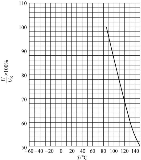
Figure 1-2 Relationship curve between operating voltage and temperature
As can be seen from Figure 1-3, when the temperature is higher than 85°C, for every 10°C increase, the applicable voltage is 90% of the voltage at 85°C. When increasing from 85°C to 105°C, the applicable voltage is 85°C. 80% of voltage at temperature.
If the capacitor core is formed at 70°C and the solid electrolytic capacitor works at 125°C, the working voltage drops to about 55% of the 70°C working voltage.
It can be seen that the higher the formation temperature of the capacitor core, the smaller the attenuation of the operating voltage at high temperatures.
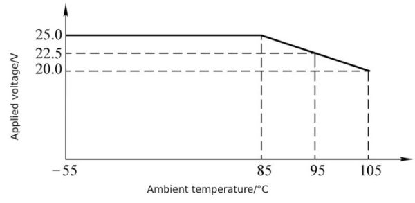
Figure 1-3 The relationship between the temperature of a 25V solid electrolytic capacitor and the external voltage that can be applied
3.1.2 Rated voltage The rated voltage UR represents the DC voltage on the capacitor and is determined by the thickness of the dielectric. Rated voltage is the maximum voltage it can withstand at rated temperature.
The rated voltage of solid aluminum electrolytic capacitors can be 2V at low voltage and up to 400V at high voltage. Most of its applications are low-voltage applications, especially mobile phone charger applications.
3.1.3 Reverse voltage Any incorrect polarity voltage caused by DC voltage and AC voltage components must be less than or equal to the allowable polarity reverse voltage.
3.1.4 Polarity mark Solid aluminum electrolytic capacitors are polar electrolytic capacitors. When using lead-pin packages, the long lead pin is the positive pole and the short lead pin is the negative pole. Since the solid aluminum electrolytic capacitor shell does not have a plastic sleeve, the polarity of the capacitor electrode is marked on the aluminum shell, and the marked one is the negative electrode, as shown in Figure 1-4.
3.2 capacitance
Capacitance is the most important parameter of a capacitor.
3.2.1 Capacitance test conditions The capacitance of solid aluminum electrolytic capacitors is the electrostatic capacitance under 120Hz test conditions.
The nominal capacitance value of solid aluminum electrolytic capacitors is the same as that of aluminum electrolytic capacitors and tantalum electrolytic capacitors, using the E12 preferred series.
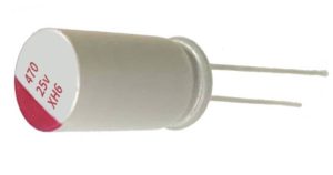
Figure 1-4 Solid aluminum electrolytic capacitor polarity mark
Solid aluminum electrolytic capacitors can have capacitances from less than one microfarad to thousands of microfarads.
3.2.2 “Temperature Characteristics” of Capacitance The relationship between capacitance and temperature obtained from the capacitor electrode terminal test is the “temperature characteristic” of capacitance, as shown in Figure 1-5.
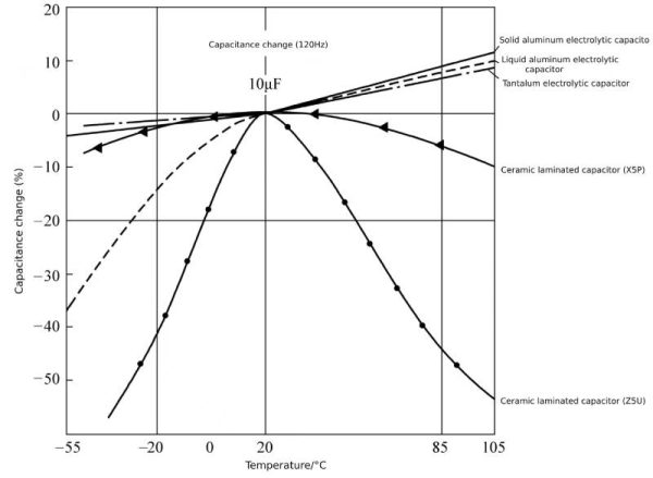 Figure 1-5 Relationship between capacitance and temperature of solid aluminum electrolytic capacitors
As can be seen from Figure 1-5, the capacitance of solid aluminum electrolytic capacitors changes less with temperature than liquid aluminum electrolytic capacitors, especially in the low temperature range.
3.3.3 Loss factor Although the ESR of solid aluminum electrolytic capacitors is much lower than that of liquid aluminum electrolytic capacitors under high-frequency testing conditions, the loss factor is tested at a frequency of 120Hz. At 120Hz frequency, the ESR of solid electrolytic capacitors mainly depends on If the aluminum oxide film of the positive electrode foil is removed, the loss factor of the solid aluminum electrolytic capacitor is close to or basically the same as that of the liquid aluminum electrolytic capacitor. The relationship between the loss factor and temperature is shown in Figure 1-6.
3.3.4 Leakage current The leakage current of solid aluminum electrolytic capacitors is caused by defects in the aluminum oxide film of the positive electrode foil, which is the same as the leakage current of liquid aluminum electrolytic capacitors. However, it should be noted that liquid aluminum electrolytic capacitors can continuously repair defects in the aluminum oxide film by continuously applying voltage to the electrolytic capacitor, but solid aluminum electrolytic capacitors do not have the ability to repair the aluminum oxide film and need to have smaller leakage current. The relationship between solid aluminum electrolytic capacitor leakage current and applied voltage is shown in Figure 1-7.
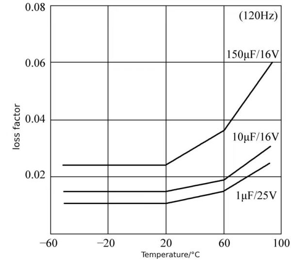 Figure 1-6 Relationship between dissipation factor and temperature of solid aluminum electrolytic capacitors
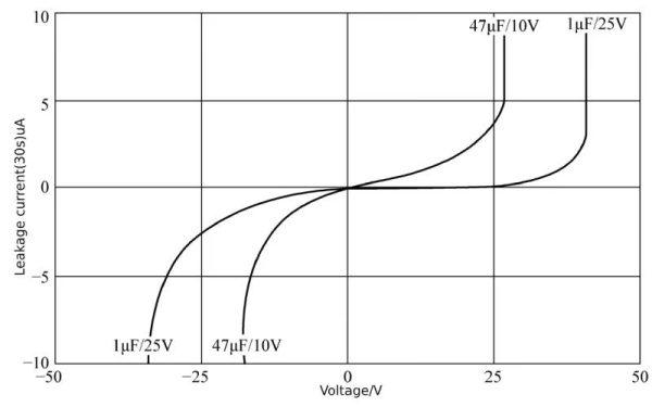 Figure 1-7 Relationship between solid aluminum electrolytic capacitor leakage current and applied voltage
The relationship between leakage current and temperature at the rated voltage of solid aluminum electrolytic capacitors is shown in Figure 1-8.
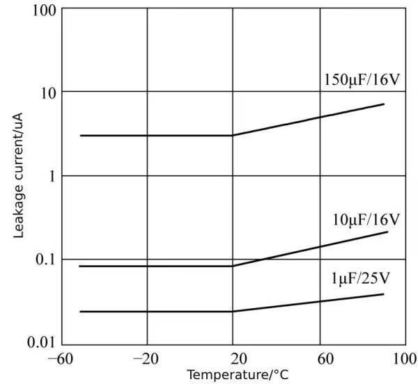 Figure 1-8 Relationship between leakage current and temperature at rated voltage of solid aluminum electrolytic capacitors
Like liquid electrolytic capacitors, the leakage current of solid aluminum electrolytic capacitors increases with temperature.
The above is an analysis of the general electrical parameters of polymer electrolytic capacitor.
4 Polymer electrolytic capacitor – impedance characteristics
4.1 Polymer electrolytic capacitor –equivalent series resistance
Similar to liquid aluminum electrolytic capacitors, the ESR of solid aluminum electrolytic capacitors is also composed of the ESR generated by the aluminum oxide film and the ESR generated by the electrolyte (or highly conductive polymer), thus producing the frequency characteristics of the ESR. The frequency characteristic curve of ESR is shown in Figure 1-9.
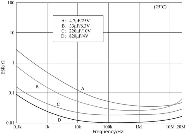 Figure 1-9 Frequency characteristic curve of ESR
As can be seen from Figure 1-9, as the frequency increases, the ESR of the solid aluminum electrolytic capacitor decreases. This characteristic is similar to the frequency characteristic of the ESR of the liquid aluminum electrolytic capacitor. Taking a 4.7μF/25V solid aluminum electrolytic capacitor as an example, the ESR at a frequency of 100Hz is about 3Ω, while the ESR in the 1 to 10MHz frequency band is about 0.05Ω. The difference between the two is about 60 times. If only considered from the same perspective as heating due to current flowing through ESR, the 100Hz ripple current of this solid aluminum electrolytic capacitor is only 13% of the 1MHz ripple current.
If you look at the 820μF/4V solid aluminum electrolytic capacitor in Figure 1-9, the ESR at 100Hz frequency is about 0.1Ω, and at 100kHz frequency it is about 0.01Ω. The difference between the two is 10 times, and the ripple current at 100Hz frequency is About 32% of the ripple current at 100kHz frequency. It should be noted that the characteristic curves in Figure 1-9 are products from 1995 to 2000. With the innovation of solid aluminum electrolytic capacitor manufacturing technology, the ESR at 100kHz frequency has also been significantly reduced. In 2020, 820μF/6.3V solid aluminum For electrolytic products, the ESR at 100kHz frequency can be reduced to 5~7mΩ, and the corresponding ripple current at 100Hz frequency is about 25% of the ripple current at 100kHz frequency. That is to say, using a highly conductive polymer as the negative electrode, under the same temperature rise conditions, the 100kHz ripple current capability of the solid aluminum electrolytic capacitor can be increased by nearly 4 times.
The ESR of liquid aluminum electrolytic capacitors changes greatly with temperature, even within an order of magnitude. The temperature characteristic curve of ESR of solid aluminum electrolytic capacitor is shown in Figure 1-10.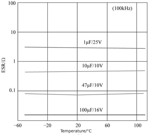 Figure 1-10 ESR temperature characteristic curve of solid aluminum electrolytic capacitor
As can be seen from Figure 6-10, the ESR of solid aluminum electrolytic capacitors at a frequency of 100kHz basically does not change with temperature, similar to tantalum electrolytic capacitors.
4.2 impedance frequency characteristics
Solid aluminum electrolytic capacitors also have impedance frequency characteristics. Figure 1-11 shows the impedance frequency characteristic curves of solid aluminum electrolytic capacitors and liquid aluminum electrolytic capacitors in the 2021 product manual of Nantong Jianghai Capacitor Co., Ltd.
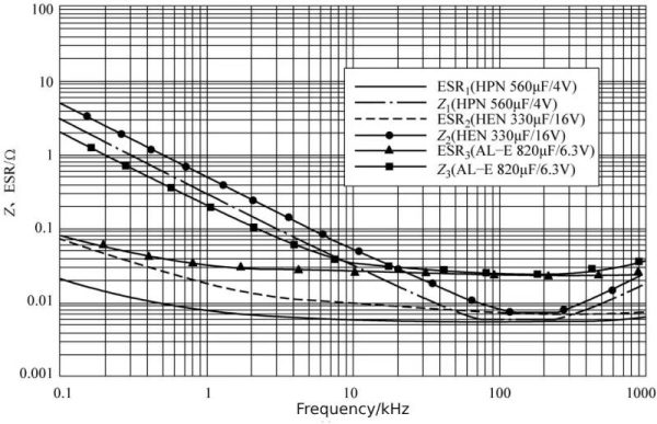 Figure 6-11 Impedance frequency characteristic curves of solid aluminum electrolytic capacitors and liquid aluminum electrolytic capacitors
In Figure 1-11, Z1 and ESR1 are the impedance frequency characteristics and ESR frequency characteristics of HPN 560μF/4V solid aluminum electrolytic capacitor, Z2 and ESR2 are the impedance frequency characteristics and ESR frequency characteristics of HEN 330μF/16V solid aluminum electrolytic capacitor, Z3, ESR3 is the impedance frequency characteristics and ESR frequency characteristics of AL-E 820μF/6.3V liquid aluminum electrolytic capacitor.
In the low frequency band (0.1~1kHz), the impedance of the electrolytic capacitor is dominated by the capacitive reactance of the capacitor, so the larger the capacitance, the lower the capacitive reactance. At this time, the liquid aluminum electrolytic capacitor with the largest capacitance (820μF/6.3V) shows the lowest impedance, the second largest capacitance (560μF/4V) solid aluminum electrolytic capacitor has the second highest impedance, and the highest impedance is the lowest capacitance 330μF. /16V solid aluminum electrolytic capacitor.
Because the ESR of liquid aluminum electrolytic capacitors is much greater than that of solid aluminum electrolytic capacitors. As the frequency increases, when the capacitive reactance of the liquid aluminum electrolytic capacitor decreases to the same order of magnitude as the ESR (above 5kHz in Figure 1-11), the ESR characteristics begin to gradually appear and are gradually higher than the capacitive reactance. At this time, the liquid aluminum electrolytic capacitor The impedance frequency characteristic begins to show flat characteristics.
At the same time, since the ESR of solid aluminum electrolytic capacitors is much smaller than that of liquid aluminum electrolytic capacitors, a higher frequency is required to reduce the capacitive reactance of solid aluminum electrolytic capacitors to the same order of magnitude as the ESR. It can be seen from Figure 1-11 that this frequency needs to be above 50kHz.
In the frequency band around 100kHz, the impedance characteristics of liquid aluminum electrolytic capacitors and solid aluminum electrolytic capacitors are both ESR characteristics. At this time, the capacitive reactance of the capacitor is much lower than the ESR. For example, the capacitive reactance of the 330μF capacitor with the lowest capacitance at the frequency of 100kHz is 4.8 mΩ, much lower than the ESR above 10mΩ.
As the frequency increases, the inductive reactance of the capacitor begins to increase to be close to the ESR, and the impedance characteristics of the capacitor begin to show inductive characteristics. Lead-pin solid aluminum electrolytic capacitors begin to exhibit inductive characteristics above 300kHz. The liquid aluminum electrolytic capacitor in Figure 1-11 has inductive impedance characteristics above 600kHz, which seems to have better high-frequency characteristics than solid aluminum electrolytic capacitors. In fact, the parasitic inductance of solid aluminum electrolytic capacitors is smaller than that of liquid aluminum electrolytic capacitors. The reason why liquid aluminum electrolytic capacitors exhibit inductive characteristics is that the ESR of liquid aluminum electrolytic capacitors is much higher than that of solid aluminum electrolytic capacitors. The inductance of the parasitic inductance needs to be close to the ESR. Or higher than ESR to show perceptual characteristics. If the ESR of the liquid aluminum electrolytic capacitor is 10 times that of the solid aluminum electrolytic capacitor and the parasitic inductance is the same, the impedance of the liquid aluminum electrolytic capacitor will be inductive and its frequency will be 10 times that of the solid aluminum electrolytic capacitor. Since solid aluminum electrolytic capacitors with the same rated voltage/capacitance are smaller and have smaller parasitic inductance, the frequency at which the liquid aluminum electrolytic capacitor in Figure 1-11 becomes inductive is not much higher than that of the solid aluminum electrolytic capacitor.
Entering the high frequency band (above 500kHz), the impedance frequency characteristics of each capacitor in Figure 1-11 all enter inductive characteristics. The capacitor impedance at this time will depend on the size of the capacitor’s parasitic inductance.
Although the impedance characteristics are inductive in the high frequency band, it does not mean that the capacitor does not have filtering characteristics. As long as the impedance is low enough, it still has good filtering characteristics.
The above is an analysis of the impedance characteristics of polymer electrolytic capacitor.
5 Polymer electrolytic capacitor – relationship between lead pin position and ESR
Since the negative electrode ESR of solid aluminum electrolytic capacitors is extremely low, the volume resistance of the aluminum foil cannot be ignored. For example, for a certain solid aluminum electrolytic capacitor, the ESR of products from different manufacturers may be quite different. Some are around 10mΩ, while others are around 8mΩ. If it is a liquid aluminum electrolytic capacitor, the ESR difference of 2mΩ seems to be negligible. After all, the ESR of the liquid aluminum electrolytic capacitor is much more affected by temperature than 2mΩ, and the ESR at room temperature is generally above 30mΩ.
The ESR of solid aluminum electrolytic capacitors almost does not change with temperature, and the ESR value is very low, which makes a difference of 2mΩ lead to a 20% difference in ESR. This difference is obvious in terms of application and durability of solid aluminum electrolytic capacitors. .
Under the same ripple current condition, the ESR increases by 20% to 30%, the capacitor loss increases by 20% to 30%, and the temperature rise will increase accordingly. Under the same temperature rise conditions, due to the 20% to 30% increase in ESR, the rated ripple current will be reduced by 10% to 14%. If the rated ripple current of a solid aluminum electrolytic capacitor is 5A, due to the increase in ESR, the actual ripple current capability will be reduced to 4.3~4.5A. This result is absolutely not allowed when the ripple current is applied to almost the limit state!
The reason for such an ESR difference is that the position of the guide pin is not at the center of the filter, but is offset to one side of the aluminum foil. Why should the guide pin be offset instead of centered? The reason is that the position of the guide pin of the electrolytic capacitor core should correspond to the position of the hole in the rubber plug. If the position of the core guide pin is inconsistent with the position of the hole in the rubber plug, the guide pin cannot enter the rubber plug. The guide pin must be offset to the foil side. In order to solve this problem, an offset guide pin appeared, which can solve the problem of offset position of the guide pin on the aluminum foil. The problem is that the guide pins are specially made, and the nailing and rolling machine needs to identify the “A” and “B” sides of the guide pins, resulting in an increase in the production cost of solid aluminum electrolytic capacitors using offset guide pins.
Based on the above problems, when the customer has no special requirements, the ESR is slightly higher using conventional manufacturing methods. If customers have higher requirements for ESR performance, offset guide pins and corresponding nailing and coiling processes are used to obtain the lowest possible ESR.
The above is an analysis of the relationship between the lead pin position and ESR of polymer electrolytic capacitor.
6 Polymer electrolytic capacitor – equivalent series inductance
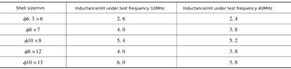
Solid aluminum electrolytic capacitors have a much lower ESL than liquid aluminum electrolytic capacitors. The ESL of solid aluminum electrolytic capacitors produced from 1995 to 2000 is shown in Table 1-1.
As can be seen from Table 1-1, the ESL of solid aluminum electrolytic capacitors is significantly less than 10nH. The ESL of no more than 10nH is almost the length of the guide pin passing through the rubber plug and the parasitic inductance generated by the surrounding space, indicating that the negative electrode of the solid aluminum electrolytic capacitor is almost integrated.
Table 1-1 ESL of solid aluminum electrolytic capacitors
To further reduce ESL, solid aluminum electrolytic capacitors need to be in lamination form. The structure of laminated solid aluminum electrolytic capacitor is shown in Figure 1-12.
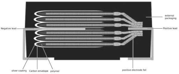
Figure 1-12 Cross-sectional view of laminated solid aluminum electrolytic capacitor
As can be seen from Figure 1-12, the electrodes of the laminated solid aluminum electrolytic capacitor are stacked, which eliminates the winding ESL of the wound electrolytic capacitor. The remaining ESL is only the terminal distance of the capacitor electrode. The physical inductance will be significantly lower than the ESL of the wound electrolytic capacitor. The impedance frequency characteristic curves of laminated solid aluminum electrolytic capacitors and wound solid aluminum electrolytic capacitors produced by the American CDE company before 2005 are shown in Figure 1-13 and Figure 1-14.
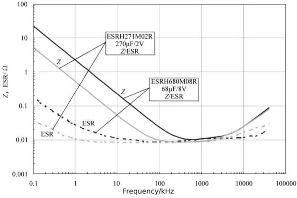
Figure 1-13 Impedance frequency characteristic curve of laminated solid electrolytic capacitor
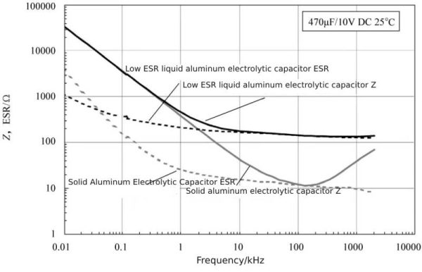
Figure 1-14 Impedance frequency characteristic curve of chip solid aluminum electrolytic capacitor
The impedance frequency characteristics of the two specifications of laminated solid aluminum electrolytic capacitors shown in Figure 1-13 enter the inductive characteristics at a frequency above 2MHz. This ESL is determined by the physical size of the laminated solid aluminum electrolytic capacitor (length is 7.3mm).
The capacitors shown in Figure 1-14 are products before 2005. The size of the low ESR liquid electrolytic capacitor is ϕ8×10mm, and the size of the solid aluminum electrolytic capacitor is ϕ10×10.2mm. Therefore, liquid aluminum electrolytic capacitors may have a lower ESL than solid aluminum electrolytic capacitors. At high frequencies (above 10MHz), since the characteristic curve does not extend to 10MHz, the difference in ESL of the two electrolytic capacitors cannot be accurately judged.
The above is an analysis of the equivalent series inductance of polymer electrolytic capacitor.
7 Polymer electrolytic capacitor – ripple current
The biggest feature of solid aluminum electrolytic capacitors is that the ESR is greatly reduced, and at the same time, the ripple current allowed to flow is greatly increased.
The test conditions for the rated ripple current of solid aluminum electrolytic capacitors are different from the test conditions for the ripple current of liquid aluminum electrolytic capacitors. The test conditions for liquid aluminum electrolytic capacitors with a maximum temperature of 105°C are that the maximum core temperature is not higher than the ambient temperature 5°C, that is, the maximum core temperature is 110°C; the test conditions for liquid aluminum electrolytic capacitors with a maximum temperature of 85°C are that the core temperature is the highest The temperature is not 10℃ higher than the ambient temperature, that is, the maximum temperature of the core is 95℃.
The rated ripple current test conditions of solid aluminum electrolytic capacitors are: 105℃ products/125℃ products, the ambient temperature is ≤105℃, the temperature rise is not higher than 20℃; 125℃ products, 105℃≤ambient temperature ≤125℃ , the temperature rise is not higher than 5℃. Compared with the 85°C liquid aluminum electrolytic capacitor test condition, the maximum core temperature is not higher than the ambient temperature 10°C, which is a 20°C increase in temperature. This makes the solid aluminum electrolytic capacitor have a rated ripple current even under the same ESR conditions. It will also be larger than the liquid aluminum electrolytic capacitor. In addition, the ESR decreases sharply. The actual rated ripple current of the solid aluminum electrolytic capacitor with the same rated voltage and capacitance is at least 5 times higher, or even higher.
Table 1-2 shows the data of various aluminum electrolytic capacitors with the same capacitance (1000μF/16V).
Table 1-2 Data of various types of aluminum electrolytic capacitors of 1000μF/16V
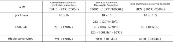
In actual data, the ESR of the HEN type solid aluminum electrolytic capacitor reaches 10mΩ when the capacitance is 270μF, and the ripple current reaches 6100mA when the capacitance is 330μF.
Among low-ESR liquid aluminum electrolytic capacitors, CD285 is the model with the lowest ESR and the largest ripple current. The ESR is 38mΩ and the ripple current is 2000mA.
The general-purpose liquid aluminum electrolytic capacitor CD110 series has an ESR of 210mΩ at a frequency of 120Hz, and no ESR value at a frequency of 100kHz is given. The ripple current is 791mA (120Hz) converted to 950mA at 100kHz frequency.
Through comparison, it can be seen that solid aluminum electrolytic capacitors have ultra-low ESR and ultra-high ripple current tolerance capabilities that are unmatched by other types of electrolytic capacitors under high frequency conditions, and are especially suitable for high ripple current applications.
The above is an analysis of the ripple current of polymer electrolytic capacitor.
8 Polymer electrolytic capacitor- lifespan
8.1 Polymer electrolytic capacitor –the nature of failure of solid electrolytic capacitors
Since solid aluminum electrolytic capacitors have no electrolyte, there is no failure caused by the electrolyte drying out. There are two modes of solid aluminum electrolytic capacitor failure: short circuit and loss of capacitance.
Since the negative electrode of the solid aluminum electrolytic capacitor is a highly conductive polymer, which is in close contact with the aluminum oxide film of the positive electrode foil in a solid manner, the aluminum oxide film will break when exposed to external mechanical stress, resulting in a short circuit phenomenon, even if no power is applied when the film breaks. Since the breakdown field strength of the broken part is much lower than the breakdown field strength of the aluminum oxide film, once the solid aluminum electrolytic capacitor is powered on, it will cause irreversible breakdown of the broken part of the aluminum oxide film. Another kind of breakdown is that the solid aluminum electrolytic capacitor suffers from overvoltage. Once this overvoltage exceeds the breakdown voltage of the aluminum oxide film, even if it is a very short-term overvoltage breakdown, since the solid aluminum electrolytic capacitor does not have the ability to repair the aluminum oxide film, it will Overvoltage breakdown is an irreversible breakdown.
Another way solid capacitors can fail is through significant attenuation and loss of capacitance. The reason for the capacitance fading is the failure of the highly conductive polymer, and the failure form is the decomposition of the highly conductive polymer. The cause of the decomposition of highly conductive polymers is high temperature. When the temperature exceeds 125°C, the highly conductive polymers in solid aluminum electrolytic capacitors will decompose very quickly. Appropriately lowering the temperature can effectively slow down the decomposition rate.
8.2 life test conditions
The test conditions for judging the end of life of solid aluminum electrolytic capacitors take the 105°C/2000h HPN series of solid aluminum electrolytic capacitors from Nantong Jianghai Capacitor Co., Ltd. as an example.
8.2.1 High temperature load life test
At 105°C, with rated DC voltage applied, the end-of-life conditions are: capacitance decays to 80% of the initial capacitance, loss factor increases to no more than 150% of the initial value, ESR increases to no more than 150% of the initial value, leakage The current is lower than the specified value. There is no indication in this test that ripple current needs to be applied. This test condition must pass at least a rated life of 2000h.
8.2.2 High temperature storage life test
Temperature 60℃, humidity 90%~95%, no voltage applied. The end-of-life conditions are: the capacitance decays to 80% of the initial capacitance, the loss factor increases to no more than 150% of the initial value, the ESR increases to no more than 150% of the initial value, and the leakage current is lower than the specified value.
8.2.3 Welding heating resistance
Reflow soldering (260±5)℃, 10s, the capacitance change is not greater than ±5%, the loss factor is not greater than the initial value, the ESR is not greater than the initial value, and the leakage current after applying voltage is not greater than the specified value. The above are the performance requirements of chip electrolytic capacitors after reflow soldering. If they exceed these requirements, it can be determined that the electrolytic capacitor has failed after reflow soldering.
8.3 life characteristic curve
Generally, for every 20°C decrease in temperature, the life of solid aluminum electrolytic capacitors will increase by an order of magnitude, that is, for every 10°C decrease, the lifespan increases to 3.16 times the original value. Compared with liquid aluminum electrolytic capacitors, the lifespan increases to 2 times the original value for every 10°C decrease. Especially, the more the temperature decreases, the more obvious the lifespan increases.
Figure 1-15 shows a comparison of the estimated life of liquid aluminum electrolytic capacitors and solid aluminum electrolytic capacitors at 105°C/2000h.
As can be seen from Figure 1-15, when the temperature drops to 85°C, the life of the liquid aluminum electrolytic capacitor increases to 8000h, and the life of the solid aluminum electrolytic capacitor increases to 20000h; when the temperature drops to 65°C, the life of the liquid aluminum electrolytic capacitor Increased to 32000h (equivalent to 3.5 years), the life of solid aluminum electrolytic capacitors increased to 200000h (equivalent to 23 years).
During the durability test (HPN 560μF/4V), the changing trends of capacitance, loss factor, ESR, and leakage current are shown in Figure 1-16 to Figure 1-19.
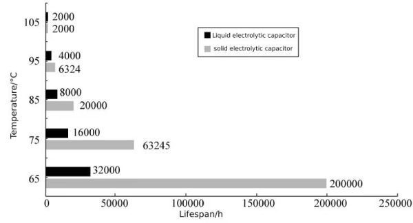
Figure 1-15 Comparison of life estimation of liquid aluminum electrolytic capacitors and solid aluminum electrolytic capacitors
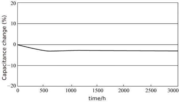 Figure 1-16 Capacitance change of solid aluminum electrolytic capacitor durability test
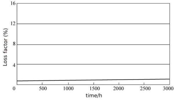 Figure 1-17 Dissipation factor changes in durability test of solid aluminum electrolytic capacitors
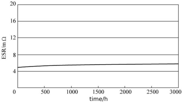
Figure 1-18 ESR changes of solid aluminum electrolytic capacitor durability test
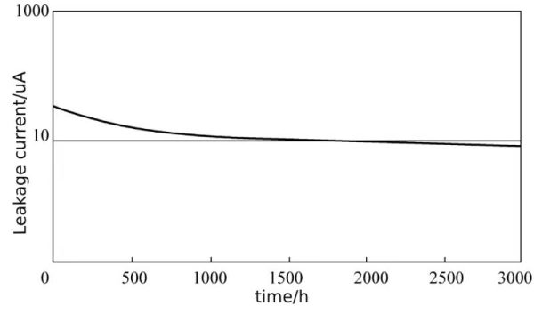 Figure 1-19 Leakage current changes in durability test of solid aluminum electrolytic capacitors
8.4 accelerated life test
How do you know that the life of solid aluminum electrolytic capacitors increases by one order of magnitude for every 20°C decrease? How do you know that the life of solid aluminum electrolytic capacitors can reach 20 years at a temperature of 65°C? The most effective way to predict long-term life is accelerated life testing. Figure 1-20 shows Sanyo’s temperature acceleration test characteristic curve.
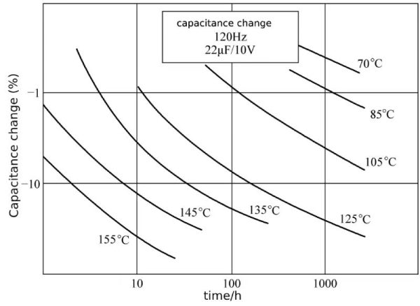 Figure 1-20 Sanyo’s temperature acceleration test characteristic curve
It can be seen from the accelerated life test that as the test temperature increases, the capacitance decay of the solid aluminum electrolytic capacitor accelerates. Calculated based on the capacitance attenuation of 20%, when the test temperature reaches 125°C, the capacitance attenuation of the 105°C product cannot support 2000h and can only be maintained for less than 600h. When the temperature rises to 135°C, the capacitance decay can only support 100h. If the temperature rises to 145°C, the capacitance decay can only be sustained for less than 20 hours. If the temperature rises to 155°C, the capacitance decay can only be sustained for less than 50 hours.
According to the rules in Figure 1-20, the life expectancy can be obtained.

In the formula, TA is the maximum ambient temperature; ΔT is the core center temperature rise caused by the actual ripple current; TO is the rated upper limit operating temperature; LO is the specified life when rated voltage is applied at the maximum temperature; LX is the actual operating temperature Estimated life under TA+ΔT.
The calculation method for the temperature rise ΔT due to internal heating caused by ripple current is:
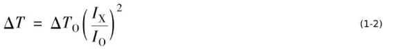
In the formula, ΔTO is the maximum temperature rise when the rated ripple current is superimposed; IO is the rated ripple current (effective value); IX is the actual ripple current (effective value). The frequencies of IO and IX must be the same, and IX≤IO .
The above is an analysis of the life of polymer electrolytic capacitor.
9 Polymer electrolytic capacitor-the negative electrode is drawn from aluminum foil to carbon foil
Since the negative electrode foil of the aluminum electrolytic capacitor is the lead-out electrode of the negative electrode, the electrolytic capacitor is actually the capacitance between the positive electrode foil and the electrolyte solution and the capacitance between the negative electrode foil and the electrolyte solution connected in series, as shown in Figure 1-21.
The reason is that the negative electrode foil has a certain formation voltage, so the relationship between the negative electrode foil and the electrolyte must be a capacitor, not a direct electrical connection. The actual capacitance is the series connection result of two capacitors, that is
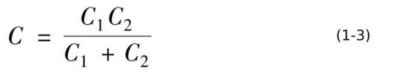
The capacitance of an ideal electrolytic capacitor should be the capacitance C1 between the positive electrode foil and the electrolyte or polymer.
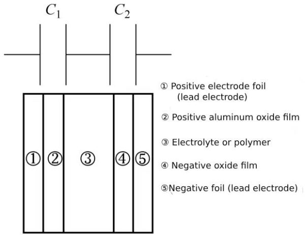
Figure 1-21 Actual aluminum electrolytic capacitor
Since there is an aluminum oxide film on the negative electrode foil, and in some cases, a sufficient voltage is required due to the performance requirements of the capacitor, forming a capacitance C2 between the electrolyte or polymer and the negative electrode foil. According to equation (1-3), when C2 is infinite, C=C1, which is an ideal result.
Due to the existence of C2, especially when the size of C2 is close to C1, the actual capacitance C will be significantly attenuated. If C2=C1, the actual capacitance decays to 1/2 of C1; if C2=2C1, the actual capacitance decays to 2/3 of C1. Both of these results are relatively unacceptable, and the specific volume of the negative electrode foil needs to be increased as much as possible.
Usually, the specific volume of the low-voltage positive foil is in the range of 23 to 77 (25Vw/33Vw) or 36 to 118 (16Vw/21Vw), and the specific volume of the negative foil with a 3V formation voltage is about 150, where Vw is the operating voltage. Such negative electrode foil will cause the external capacitance of the capacitor to attenuate by more than 30% compared to the capacitance of the positive electrode foil. If there is direct conduction between the negative electrode foil and the highly conductive polymer, there will be no negative electrode foil specific volume, which will significantly reduce the volume of the solid aluminum electrolytic capacitor. Such negative electrode foil is carbon foil. The so-called carbon foil is to apply a layer of carbon on the surface of the corroded foil, and to ensure that there is as little oxide film between the carbon and the aluminum foil as possible, forming a direct connection between carbon and aluminum. The part of the aluminum oxide film that has not been removed can be treated with hydrocarbon-containing gas at high temperature for a long time after the aluminum foil is coated with carbon, so that the carbon reacts with the aluminum oxide film to form aluminum carbide, thereby destroying the aluminum oxide film and forming a direct connection between carbon and aluminum. .
After treatment, there is no capacitance between the negative electrode foil and the polymer, so that the capacitance of the solid aluminum electrolytic capacitor is effectively improved.
At the same time, increasing the specific volume of the positive electrode foil is also a way to increase the capacitance of the solid aluminum electrolytic capacitor. The specific volume of the positive electrode foil of the solid aluminum electrolytic capacitor is about 20% higher than that of the positive electrode foil of the liquid electrolytic capacitor with the same rated voltage.
The above is an analysis of the negative electrode lead of polymer electrolytic capacitor from aluminum foil to carbon foil.
10 Polymer electrolytic capacitor – things to note
When using solid aluminum electrolytic capacitors, in order to give full play to their performance with stable quality, the following points need to be paid attention to in circuit design.
10.1 Polymer electrolytic capacitor –polarity
Like other electrolytic capacitors, solid aluminum electrolytic capacitors have polarity. If the polarity is connected incorrectly, leakage current will increase during use or service life will be shortened. Therefore, in high-impedance circuits, coupling circuits, timing circuits (the capacitance changes that may be caused by changes in temperature will be beyond the scope of the circuit) and circuits that are greatly affected by leakage current (the voltage of each single capacitor in series may be due to The leakage current is inconsistent and cannot be equally divided) and should be prohibited from being used to prevent erroneous operating results.
10.2 Confirm rated performance
Confirm whether the application environment meets the application environment range given by the data. The main ones are: the terminal voltage cannot exceed the rated voltage, even for an instant; the applied temperature environment should be within the range given by the data, whether it is the highest temperature or the lowest temperature. must not exceed; the flowing ripple current must not exceed the rated ripple current, otherwise the inside of the capacitor will be overheated due to excessive current flowing through the ESR, reducing its service life.
10.3 limitations of applied voltage
Solid aluminum electrolytic capacitors above 25V will not cause problems if 100% of the rated voltage is applied; those of 25V and below are similar to tantalum electrolytic capacitors. When the ambient temperature exceeds 85°C, the voltage should be derated for use. When the temperature rises to 105°C, the voltage should be reduced. to 75%; the sum of DC voltage and ripple voltage shall not exceed the rated voltage; when the DC voltage is low, it should be noted that the reverse voltage caused by the ripple voltage shall not exceed 10% of the rated voltage; during the transition period such as cutting off the power supply and switching the power supply, The reverse voltage that occurs must not exceed 20% of the rated voltage, but Sanyo’s SVPD series must not apply reverse voltage.
10.4 limitations of charge and discharge current
Excessive inrush current generated by power-on or rapid charge and discharge due to other reasons may increase the leakage current of solid aluminum electrolytic capacitors or even cause internal short circuits. Therefore, when the peak impulse current exceeds 1A or exceeds 10 times the rated ripple current, a protection circuit should be used to improve the reliability of the circuit; a 1kΩ protection resistor must be connected in series when testing leakage current.
10.5 failure and service life
Please refer to the relevant data of each manufacturer for the failure rate when using solid aluminum electrolytic capacitors. Although the failure rate in use is very low, there is still the possibility of failure. Therefore, equipment using solid aluminum electrolytic capacitors is limited to cases where failure will not directly lead to casualties, etc., or where failure will not cause problems.
Typical failures of aluminum polymers are as follows.
10.5.1 Sporadic faults: Sporadic faults of solid aluminum electrolytic capacitors are mainly short circuit faults. For resin-encapsulated solid aluminum electrolytic capacitors, when a short circuit occurs, if the energizing current after the short circuit is small (ϕ10 is about 3A or less, ϕ6 is about 1A or less), although the solid aluminum electrolytic capacitor will generate some heat at this time, even if it is continuously powered, the appearance will be poor. There is no abnormality, but when the current exceeds the above value, the internal temperature of the solid aluminum electrolytic capacitor will rise. If the temperature reaches above 200°C, the organic semiconductor used as the negative electrode will melt and generate a large amount of gas. The internal pressure will rise, and the molten organic semiconductor will The odorous gas flows out from the gaps between the sealing material, the aluminum shell and the lead terminals. Do not bring your face or hands close to each other at this time to avoid burns. When a rubber-encapsulated solid aluminum electrolytic capacitor is short-circuited, if the energizing current after the short-circuit is small (ϕ10 is about 1A or less, ϕ8 is about 0.5A or less, ϕ6 is about 0.2A or less), the capacitor will generate some heat, and the appearance will not be abnormal when it is continuously energized. But when the current exceeds the above value, the internal temperature of the solid aluminum electrolytic capacitor will rise, the sealing material of the rubber product will be rolled, and the smell will leak out. At this time, the face and hands are also not allowed to be close to avoid burns. In fact, such solid aluminum electrolytic capacitors have expired and cannot be used anymore.
When using equipment equipped with solid aluminum electrolytic capacitors, if a short circuit occurs and odorous gas escapes, the power supply should be cut off; it generally takes several seconds to minutes from the occurrence of the short circuit to the occurrence of odorous gas. If a protection circuit is used, it should be followed Start designing during this time; when the generated gas enters the eyes or is inhaled into the mouth, rinse with water or gargle immediately; do not come into contact with the electrolyte of the solid aluminum electrolytic capacitor, and rinse with soap when the electrolyte adheres to the skin.
The electrolyte, electrolytic paper, plastic sleeve, packaging rubber, and base used in solid aluminum electrolytic capacitors are all flammable substances and are flammable. When the current after a short circuit is extremely large, in the worst case, clicking the terminal or the short-circuited part inside the capacitor may generate an electric spark, which can ignite the flammable material in the capacitor. Therefore, attention should be paid to the installation method, installation location and structural design of the capacitor.
10.5.2 Changes in electrical performance during use and failures due to service life: Similar to aluminum electrolytic capacitors, solid aluminum electrolytic capacitors will reduce their capacitance over time even if they are used according to the data given in the data sheet. Performance degradation such as ESR increase and ESR increase should be paid attention to during design. The life problem is mainly due to the deterioration of parameters such as large capacity and ESR after prolonged use, high temperature or high humidity for several hours, causing the negative electrode of the electrolyte to age and eventually appear in an “open circuit” state.
Solid aluminum electrolytic capacitors will increase leakage current due to reasons such as welding, storage, high temperature, and high humidity. Similar to aluminum electrolytic capacitors, they can be energized by applying a DC voltage to reduce the leakage current to the initial value. No matter what causes the leakage current to increase, this energizing method can be used to reduce the leakage current for qualified solid aluminum electrolytic capacitors. The change of leakage current during the charging process of solid aluminum electrolytic capacitor is shown in Figure 1-22.
As can be seen from Figure 1-22, the empowerment effect under high temperature is good and the time is short.
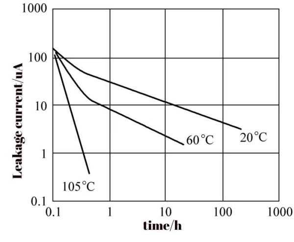 Figure 1-22 Leakage current changes during the charging process of solid aluminum electrolytic capacitors
When the ripple voltage frequency exceeds 500kHz, “compensation” measures should be taken to reduce the ripple current below the rated value.
It should be noted that since the ESR of highly conductive polymer electrolytic capacitor is much lower than other types of electrolytic capacitors, solid aluminum electrolytic capacitors should not be connected in parallel with other types of electrolytic capacitors because they will cause flow problems when connected in parallel due to the minimum ESR of solid aluminum electrolytic capacitors. The ripple current passed is the maximum.
Similar to tantalum electrolytic capacitors with liquid negative electrodes, solid aluminum electrolytic capacitors that have been deformed or dropped must not be used.
11 Polymer electrolytic capacitor – Problems raised about solid-liquid hybrid electrolytic capacitors
11.1 Polymer electrolytic capacitor -vibration issues
Solid aluminum electrolytic capacitors have very excellent performance, but they cannot be used in automotive electronic equipment. The reason is that after the solid aluminum electrolytic capacitor is subjected to vibration, the solid highly conductive polymer in close contact with the positive electrode foil may cause the aluminum oxide film to rupture, thereby causing the solid The aluminum electrolytic capacitor failed due to short circuit. Therefore, the instructions for use of solid electrolytic capacitors specifically state that vibration needs to be avoided during application.
Liquid aluminum electrolytic capacitors can have good anti-seismic performance by fixing the core and the shell relatively well. The reason is that the positive electrode foil in the liquid aluminum electrolytic capacitor is in close contact with the electrolyte, and the electrolyte will not damage the positive electrode foil during vibration. aluminum oxide film.
11.2 aluminum oxide film repair problem
The second problem with solid aluminum electrolytic capacitors is that since there is no electrolyte, they do not have the ability to repair the aluminum oxide film of liquid aluminum electrolytic capacitors. However, aluminum is a metal with very active chemical properties. If other metal impurities are present in the positive electrode foil, it will form a galvanic cell effect and even destroy the aluminum oxide film, leading to irreversible failure of the solid aluminum electrolytic capacitor.
If an electrolytic capacitor is manufactured that has the extremely low ESR and high ripple current tolerance of solid aluminum electrolytic capacitors as well as shock resistance and the ability to repair damaged aluminum oxide films, it will be compatible with solid aluminum electrolytic capacitors and liquid aluminum. The advantages of electrolytic capacitors are especially suitable for use in the field of automotive electronics, electrolytic capacitors that meet vehicle regulations with extremely low ESR, high ripple current tolerance, and anti-vibration capabilities. With the rapid development of automotive electronics, the demand for high-performance automotive grade electrolytic capacitors is increasing, and solid-liquid hybrid aluminum electrolytic capacitors have emerged.
11.3 the basic idea of solid-liquid hybrid aluminum electrolytic capacitor
Solid-liquid hybrid aluminum electrolytic capacitors can be thought of as polymerizing and breaking a highly conductive polymer outside the core, loading it with a solvent into the electrolytic capacitor core, and then evaporating the solvent to obtain a solid aluminum electrolytic capacitor core, and then impregnating the core with electrolytic liquid to form a solid aluminum electrolytic capacitor with electrolyte.
Problems that need to be solved: Carbon foil can be used as the negative electrode of solid aluminum electrolytic capacitors to eliminate the problem of specific volume of the negative electrode foil that causes the actual capacitance of the solid aluminum electrolytic capacitor to be lower than the capacitance of the positive electrode foil.
Carbon foil will not be suitable in liquid aluminum electrolytic capacitors, because the negative electrode of liquid aluminum electrolytic capacitors is ionically conductive, not electronically conductive. The ionic conductivity between the carbon foil and the electrolyte cannot be completed well, causing the carbon foil to be in the electrolyte. The specific volume is very low.
To obtain a solid-liquid hybrid aluminum electrolytic capacitor, you can go back to using aluminum foil as the negative electrode foil. The problem is that the capacitance of the capacitor is significantly lower than the capacitance of the positive electrode foil.
In order to solve this problem, people use titanium foil, that is, titanium oxide is coated on the negative electrode foil, and titanium oxide is used to connect the electrolyte and highly conductive polymer. Since titanium foil has a very high specific volume, laboratory tests can even reach 3000. Even if calculated as 1000 in actual applications, compared with the specific volume of the cathode foil of the order of 100, the resulting capacitance attenuation is negligible. In 2022, my country will be able to produce titanium foil for electrolytic capacitors.
12 Polymer electrolytic capacitor-solid-liquid hybrid capacitor performance analysis
Domestic solid-liquid hybrid aluminum electrolytic capacitors are mainly suitable for vehicle-mounted electronic equipment, so they need to be adapted to the vehicle voltage. They are generally in the voltage levels of 25V, 35V, 50V, 63V, and 80V. If the voltage is lower than 25V, it will not be suitable for vehicle-mounted electronic equipment.
In order to adapt to the requirements of automotive application environments, the operating temperature range of domestic solid-liquid hybrid aluminum electrolytic capacitors is -55~105℃ or -55~125℃. In order to adapt to the long life of the car, the solid-liquid hybrid aluminum electrolytic capacitor also needs to have a relatively long life, at least 5000h or longer.
Solid-liquid hybrid aluminum electrolytic capacitors have much lower ESR and high ripple current tolerance than liquid aluminum electrolytic capacitors. Table 1-3 shows the comparison of ESR and ripple current of different types of aluminum electrolytic capacitors.
Table 1-3 Comparison of ESR and ripple current of different types of 25V/330μF aluminum electrolytic capacitors
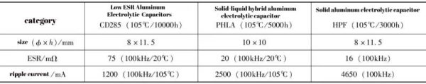
As can be seen from Table 1-3, the ESR of solid-liquid hybrid aluminum electrolytic capacitors is only 27% of the best-performing liquid aluminum electrolytic capacitors and 125% of solid aluminum electrolytic capacitors. The rated ripple current of solid-liquid hybrid aluminum electrolytic capacitors is 208% of liquid aluminum electrolytic capacitors and 54% of solid aluminum electrolytic capacitors.
Multiplication factor for ripple current. There is a highly conductive polymer negative electrode in the solid-liquid hybrid aluminum electrolytic capacitor, and the ripple current tolerance will be as sensitive to low-frequency ripple current as the solid aluminum electrolytic capacitor. Table 1-4 shows the ripple current frequency conversion coefficients of different types of 25V/330μF aluminum electrolytic capacitors.
Table 1-4 Ripple current frequency conversion coefficients of different types of 25V/330μF aluminum electrolytic capacitors
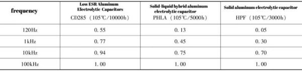
As can be seen from Table 1-4, solid aluminum electrolytic capacitors are the most sensitive to low-frequency ripple current tolerance, followed by solid-liquid mixed aluminum electrolytic capacitors, and liquid aluminum electrolytic capacitors are relatively least sensitive.
If the 120Hz frequency ripple current is 1 for comparison, Table 1-5 can be obtained.
Table 1-5 Ripple current frequency conversion coefficients of different types of 25V/330μF aluminum electrolytic capacitors
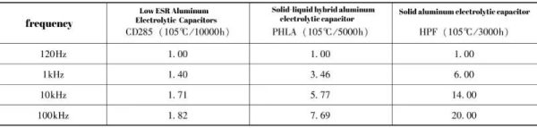
As can be seen from Table 1-5, highly conductive polymers make a huge contribution to the high-frequency ripple current withstand capability. Since most low-voltage applications are DC power supply bypass or output filtering of DC/DC converters, the ripple current The frequencies are all high frequencies, and there is almost no low-frequency ripple current of 100Hz or even 1kHz. Even if there is, its component will be very low. Therefore, improving the ESR and ripple current capability under high frequency conditions is the main development trend of low-voltage electrolytic capacitors.
Summarize:
Polymer electrolytic capacitors – performance analysis mainly includes a brief description of the manufacturing process of highly conductive polymer electrolytic capacitors, general electrical parameters of solid electrolytic capacitors, the relationship between guide pin position and ESR, lifespan and performance analysis of solid-liquid hybrid capacitors, etc. If you want to know more For more electrolytic capacitor products and knowledge, please click::http://xuansncapacitor.com