Capacitors are an indispensable component of electronic circuits and can also be found in many electrical equipment. Our daily lives are inseparable from electronic circuits, and of course we cannot do without capacitors. In this chapter, we will discuss the development of electrolytic capacitors in China.
1.1 Source of capacitors
As we all know, capacitors are one of the three major passive components (resistance, capacitance, and inductance) and are indispensable components in the fields of electrical technology and electronic technology. However, in the early days of capacitor application, when electrical technology was still at its dawn, capacitors were basically useless. Therefore, in addition to scientific experiments and scientific research, the earliest capacitors were used for entertainment.
1. The earliest capacitors were used for entertainment
The earliest capacitor was the “Leyden jar”, as shown in Figure 1-1, which consisted of applying tin foil to the inner and outer walls of the glass bottle to form two electrodes.
In 1745, Musschenbroek (1692-1761), a professor at Leiden University in the Netherlands, accidentally dropped a charged iron nail into a glass bottle while doing electrical experiments. He thought that soon the electricity in the iron nail would After a while, he wanted to take out the iron nail, but when he picked up the bottle on the table with one hand and just touched the iron nail with the other hand, he suddenly felt an electric shock-like vibration. Is this because the electricity on the nails did not run away, or is his nerves too sensitive? So he repeated the same method several times, and the results of each experiment were the same as the first time, so he I am very happy to come to a conclusion: if you put a charged object in a glass bottle, the electricity will not run away, so you can store the electricity.
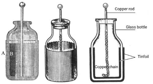 Figure 1-1 Leyden jar
Another book records this: In 1745, Musschenbroek (1692-1761), a professor at Leiden University in the Netherlands, invented the Leyden bottle. He did such an experiment. He suspended a gun barrel in the air, connected the motor to the barrel, and asked his assistant to hold the glass bottle and crank up the motor himself. At this time, his assistant accidentally touched the barrel with his other hand. Suddenly he felt a strong electric shock and screamed. So he exchanged positions with his assistant. The assistant cranked up the motor and held the bottle with one hand while touching the barrel with the other. The strong electric shock made him think: Now I am finished! His conclusion was: Put the charged object in the glass bottle. The electricity could be saved, but he didn’t know at the time whether it was the bottle or the water in the bottle that was responsible for preserving the electricity.
At that time, Leyden jars were just entertainment tools or toys. Because in those days, capacitors had no use.
The largest of these electrical demonstrations was probably the one performed by Frenchman Nolet (1700-1770) outside Notre Dame Cathedral in 1748 in front of 700 members of the royal family of King Louis XV of France. He asked 700 people to line up hand in hand. The person at the front of the line held the Leyden bottle with his hand, and the person at the end of the line held the lead of the Leyden bottle with his hand. Then he used a generator to electrify the Leyden bottle. When the motor was shaken, the 700 people jumped up almost simultaneously due to the electric shock, as shown in Figure 1-2, which made everyone present stunned!
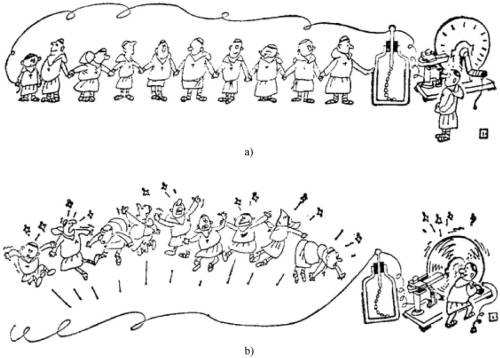 Figure 1-2 Leyden jar was first used in entertainment
2. Electrical technology and electronic technology make capacitors practical
Vacuum tubes brought a revolution in radio technology. In 1912, vacuum tubes were used to realize practical electronic circuits. Capacitors began to have more and more applications. Capacitors of various media appeared, such as air capacitors, vacuum capacitors, mica capacitors, paper capacitors, etc. Dielectric capacitors, ceramic capacitors, electrolytic capacitors, organic film capacitors, etc.
The first application of capacitors was as a resonant and timing component, which was common in the original electronic equipment for radio transmission and reception.
The second application of capacitors is to “smooth” the rectified “DC” voltage to meet the application requirements in the process of converting power frequency AC power to DC power. In this state, a relatively large capacitance and sufficient working voltage are required.
The third application of capacitors is as a power supply bypass to bypass the AC current component that the electronic circuit requires from the DC power supply when it is working to ensure the DC power quality of the electronic circuit.
The fourth application of capacitors is reactive power compensation for AC power grids. Before the rise of modern power electronics technology, reactive power compensation capacitors had the highest output value.
For electrolytic capacitors, due to polarity restrictions, most of them are used in DC voltage states, at least the terminal voltage cannot reverse polarity. Therefore, for the second of the four applications mentioned above, electrolytic capacitors are the best choice. Second applications often require electrolytic capacitors as well.
1.2 Electrolytic capacitors are a product needed by the times
Demand promotes technological development. The emergence of vacuum tubes ushered mankind into the electronic age. The three-phase AC power generation/transmission technology invented by Tesla brought mankind into the electrical age. With the increasing number of applications of radio transmitting and receiving equipment, the use of batteries has become an extremely uneconomical choice. Converting relatively cheap and relatively powerful alternating current into direct current has become an inevitable choice for electronic circuits. The circuit unit that completes this function is the rectifier filter circuit. Although this circuit is simple and has been used for nearly 100 years, it is still an irreplaceable form of circuit and energy conversion.
The rectifier circuit uses the unidirectional conduction characteristics of the diode to retain the positive half-cycle voltage of the alternating current and flip its negative half-cycle voltage to positive voltage polarity to obtain the “absolute value” of the sine wave voltage. Complete the rectification function of converting alternating current into “direct current”.
If no measures are taken, the rectified output voltage will be pulsating DC, as shown in Figure 1-3
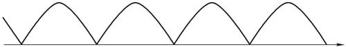
Figure 1-3 Pulsating DC voltage waveform of rectified output
Such a voltage waveform cannot meet the requirements of electronic circuits for DC power supply. Such voltage waveforms need to be smoothed. The simplest way is to use the capacitor’s voltage non-jump characteristics and voltage holding characteristics to smooth the pulsating DC power into a relatively stable DC power.
For 50/60Hz low-frequency alternating current, in order to smooth the rectified DC voltage better, a larger capacitance capacitor is needed. If paper capacitors were used at that time, they would be very large and expensive. This required a capacitor that only had requirements for operating voltage and capacitance, which was the electrolytic capacitor that came out later.
After the first electronic circuit came out in 1912, liquid aluminum electrolytic capacitors appeared nine years later in 1921. Around 1938, they were improved to dry aluminum electrolytic capacitors made of porous paper impregnated with conductive paste. In 1949, liquid sintered tantalum electrolytic capacitors appeared. In 1956 Solid sintered tantalum electrolytic capacitors were made in 2000, and solid polymer conductive polymer aluminum electrolytic capacitors appeared at the end of the 20th century. Different forms of electrolytic capacitors have different characteristics to suit different needs.
1.3 The original electrolytic capacitor
The early applied electrolytic capacitors were dry aluminum electrolytic capacitors made of porous paper impregnated with conductive paste. Such electrolytic capacitors can be seen in vacuum tube radios from the 1950s and even the 1970s.
The early packaging of aluminum electrolytic capacitors was paper tube packaging with axial leads. This packaging method is very suitable for the wiring frame overlapping method of vacuum tube circuits, as shown in Figure 1-4.

Figure 1-4 Old-fashioned paper aluminum electrolytic capacitor
In that era, aluminum was relatively expensive, and the casings of electrolytic capacitors were usually wax-impregnated paper tubes with both ends sealed with resin. Still, its sealing is far inferior to that of aluminum-cased electrolytic capacitors. Therefore, it is often seen that this type of electrolytic capacitor will fail after a period of time. The phenomenon is that the electrolyte dries up.
The shell of an electrolytic capacitor encapsulated in an aluminum shell is the negative electrode, and one terminal is the positive electrode. This packaging method is suitable for the base grounding method of vacuum tubes. The shell can be directly fixed on the base of the electronic device, similar to the grounding of a car battery. It is used when the current is not large, and its appearance is shown in Figure 1-5.
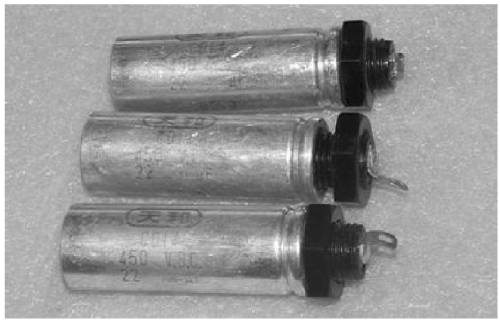
Figure 1-5 Old aluminum shell electrolytic capacitor
During this period, the positive electrode foil of the electrolytic capacitor only used a simple etching process. The capacitance per unit area of the aluminum foil (hereinafter referred to as the specific capacity) was relatively low. The production was relatively simple and could be applied to general vacuum tube electronic circuits regardless of volume.
1.4 Transistor circuits require small electrolytic capacitors
After electronic circuits entered the era of transistors, since the size of transistors is much smaller than vacuum tubes, resistors, capacitors, inductors, connectors, switches, etc. in transistor circuits all need to be small in size. Corresponding electrolytic capacitors must be miniaturized.
The miniaturization of electrolytic capacitors requires increasing the specific volume of the positive electrode foil, so the era of electrolytic corrosion has entered. At that time, miniaturized electrolytic capacitors could be seen in handheld transistor radios. Although they were much larger than today’s electrolytic capacitors, they were much smaller than the electrolytic capacitors of the vacuum tube era.
In the late 1970s and early 1980s, black and white TV sets became popular in my country. Miniaturized electrolytic capacitors have developed rapidly, quickly eliminating the early electrolytic capacitors matched with vacuum tubes.
Since the early 1990s, color TVs have become popular in my country. Its power consumption has increased from about 20W of a black and white TV to 60W. At this time, the 12V DC power supply method using a linear regulated power supply is no longer suitable because it requires a bulky power frequency transformer and large filter components. Instead, it is powered by a 220V direct rectified and filtered switching regulated power supply, which requires a withstand voltage of 400V. high voltage electrolytic capacitors.
Initially, my country’s electrolytic capacitor manufacturing technology was not able to produce miniaturized high-voltage electrolytic capacitors, so foreign electrolytic capacitors could only be used. Compared with today’s high-voltage electrolytic capacitors, the high-voltage electrolytic capacitors used in color TVs at that time were still very expensive. Despite this, the main failure of television sets at that time was the failure of electrolytic capacitors. It can be seen that the performance of electrolytic capacitors is advancing with the times and cannot be achieved by one manufacturer from the beginning. Through the unremitting efforts of our country’s researchers and manufacturers and the strong support of domestic communication manufacturers, by the early 1990s, our country was able to manufacture high-voltage electrolytic capacitors suitable for color TV sets. Later, 85°C/2000h high-voltage electrolytic capacitors could be manufactured. Around 2005, the minimum threshold for domestic electrolytic capacitor manufacturing was 85C/2000h or 105°C/2000h, that is, general-purpose electrolytic capacitors or general-purpose electrolytic capacitors.
With the continuous emergence of new electronic circuits, the size of electrolytic capacitors is required to continue to shrink. For example, the 1000uF/50V electrolytic capacitor in the vacuum tube era was 35mmx60mm in size, and the electrodes were leaded out using solder tabs, while the current leaded structure size of electrolytic capacitors is 12.5mmx25mm.
1.5 Changes in packaging forms of electrolytic capacitors
In the process of improving electrolytic capacitors, the packaging form of electrolytic capacitors has also changed. Small electrolytic capacitors have changed from the past packaging method of wax tube packaging, with the negative electrode being an aluminum shell and the positive electrode being a solder tab, to the current axial lead method, as shown in Figure 1-6.

Figure 1-6 Axial lead type small electrolytic capacitor
The advantage of this packaging form is that it is firmly installed. It is mostly used in European and American electronic circuits. The disadvantage is that the manufacturing process is relatively troublesome and the cost is relatively high.
With the commercialization of electronic circuits, as a matter of business competition, the cost of each component in the electronic circuit is required to be as low as possible. Japan has adopted the same-side lead method, as shown in Figure 1-7.
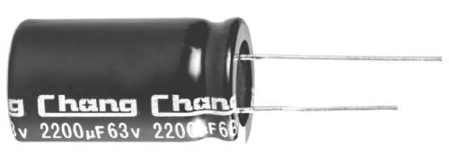
Figure 1-7 Same-side leaded electrolytic capacitor
The same-side lead type electrolytic capacitor is convenient for mechanized mass production and has low production cost. At the same time, it can also reduce the area occupied by the electrolytic capacitor on the circuit board, which is beneficial to reducing the size of the electronic circuit. In the competition for small electrolytic capacitor packaging, ipsilateral leaded electrolytic capacitors defeated axial leaded electrolytic capacitors. Domestic small electrolytic capacitors mostly use the same-side lead method. At the same time, the size of capacitors is constantly decreasing. For example, the size of a 10uF/400V electrolytic capacitor when packaged in a wax tube is about 25mmx60mm (excluding leads). 20 years ago, the size of the same-side leaded electrolytic capacitor of the same specification was about 12.5mmx20mm. Now it only needs 10mmx 16mm, or even a small size. It can reach 8mmx16mm or 10mmx12.5mm.
Large-capacity electrolytic capacitors are unreliable only by two leads and require a stronger fixing method. Early large-capacity electrolytic capacitors were solder-type and fixed with clips. For transistor electronic circuits and integrated circuits, this installation method is not suitable and a simpler installation method is required. It is best to solder directly to the circuit board and fix the electrolytic capacitor with soldered pins, which requires relatively strong pins. . The most common is the “horn” type electrolytic capacitor. The lead wires of this kind of electrolytic capacitor are relatively thick pins on the same side. In order to be firmly fixed on the circuit board under wave soldering conditions, the pins are curved to hook into the soldering holes of the circuit board and prevent them from falling off. This kind of pin looks like a horn, so it is called a “horn” type electrolytic capacitor, as shown in Figure 1-8.
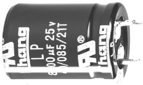
Figure 1-8 “Horn” type electrolytic capacitor
When the electrolytic capacitor is larger, the mechanical strength of the two pins is not enough, and it needs to be fixed with four or five pins, as shown in Figure 1-9a and Figure 1-9b.
Usually, since electrolytic capacitors only require two pins as electrodes, four-pin “horn” type electrolytic capacitors have two pins that are not connected internally to the positive and negative poles. However, due to the presence of electrolyte inside the electrolytic capacitor, the pins without internal connections can be considered to be at the same potential as the negative electrode, but they cannot withstand current as electrodes.
Nowadays, the “horn” type electrolytic capacitor can reach a maximum of 2200uF/400V. Large “horn” type electrolytic capacitors are much cheaper than bolt type electrolytic capacitors.
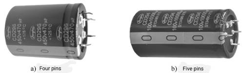
a) Four pins b) Five pins
Figure 1-9 Multi-pin electrolytic capacitor
In addition to the four-pin method for large “horn” type electrolytic capacitors, new plug-type electrolytic capacitors have appeared in recent years. Since the mechanical strength of the plug is much greater than the pins, and the two plugs are installed in a 90° vertical direction, they can Get stronger mounting strength than four-pin electrolytic capacitors. The chip electrolytic capacitor is shown in Figure 1-10
When the capacitance continues to increase and the pins of the “horn” type electrolytic capacitor cannot reliably fix the electrolytic capacitor, a stronger packaging form that can pass a larger current is needed. This is a bolt-type electrolytic capacitor, as shown in Figure 1-11 Bolt-type electrolytic capacitors are usually not fixed with electrode bolts, but with clips, so the more famous electrolytic capacitor manufacturers will sell clips together with electrolytic capacitors. Bolt-type electrolytic capacitors can even be 10 mF/450V or 3F/16V. The size can be about 100mm in diameter and nearly 250mm in height. If larger electrolytic capacitors are needed, multiple capacitors need to be connected in parallel, at least for now.
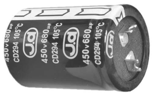
Figure 1-10 Chip electrolytic capacitor
After the assembly of electronic components entered the patch mode, electrolytic capacitors were also required to meet the requirements of the patch. Electrolytic capacitors in patch packaging came into being, as shown in Figure 1-12.
.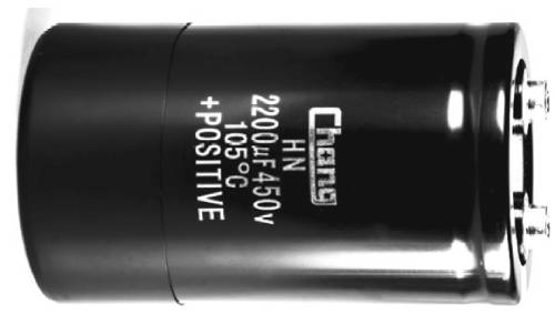
Figure 1-11 Bolt type electrolytic capacitor
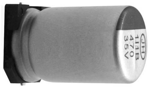
Figure 1-12 SMD packaged electrolytic capacitor
The above-mentioned electrolytic capacitors are all wound and have a large parasitic inductance, while capacitors in the form of lamination (i.e., the packaging form of MLCC or patch type platinum electrolytic capacitors) have very low parasitic inductance. In order to reduce the parasitic inductance of electrolytic capacitors Inductance, to improve the frequency performance of electrolytic capacitors, requires the capacitors to be packaged in the form of chip platinum electrolytic capacitors. The laminated electrolytic capacitor is shown in Figure 1-13.
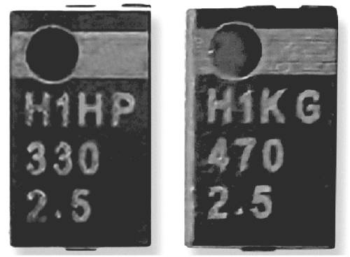
Figure 1-13 Laminated electrolytic capacitor
The electrolytic capacitor package also determines the current capability the electrolytic capacitor can withstand. For example, a lead-type electrolytic capacitor has only one conductor pin per electrode, while a “horn”-type electrolytic capacitor has at least two conductor bars per electrode. Each electrode of a bolt-type electrolytic capacitor can have more conductors depending on the current flowing through it. Streams.
Obviously, when each electrode has only one guide pin, the corresponding current carrying capacity is relatively minimal. The “horn” type electrolytic capacitor has at least two conductor bars, and the current carrying capacity is definitely greater than that of only one conductor pin, and more conductor bars will increase the current carrying capacity exponentially.
It is believed that if electrolytic capacitors require higher current carrying capacity in the future, electrode conduction methods and new packaging forms with higher current carrying capacity will inevitably appear.
1.6 Innovation of electrolyte
The main component of the early electrolyte was boric acid, which had a relatively large resistivity and did not need to consider flash voltage issues. Since the specific volume of the positive electrode foil is very low, a large amount of aluminum foil is needed to obtain the required capacitance. Therefore, the contact area between the electrolyte and the filter is relatively large, which objectively basically offsets the problem of high resistivity of the electrolyte.
Since the early electrolytic capacitors were relatively large in size and had relatively good heat dissipation capabilities, and the ripple current generated by the electronic circuits at that time was relatively small, the temperature rise of the heat was relatively low and there was no need to consider heat dissipation issues during use. Due to the existence of the rectifier transformer, the rectifier The ripple current generated by filtering is also smaller than the 100Hz ripple current generated by current 220V direct rectification.
The maximum operating temperature of early electrolytic capacitors was only 55°C. As the volume of electrolytic capacitors is greatly reduced, the area of aluminum foil is greatly reduced, and the area where the electrolyte contacts the filter is also greatly reduced. At the same time, electrolytic capacitors need to be able to withstand increasing currents. The original high-resistivity electrolyte can no longer meet the new needs, and the resistivity needs to be reduced as much as possible. At the same time, according to application requirements, the application temperature of electrolytic capacitors must be broadened.
The current electrolyte uses ethylene glycol as the solvent, and then adds the required additives according to different application requirements.
As the operating temperature of electrolytic capacitors rises to 125°C or even above 13°C, the solvent of the electrolyte of high-voltage electrolytic capacitors is changed to ethylene glycol + diethylene glycol. For low-voltage electrolytic capacitors that need to meet -55°C, The solvent for the electrolyte requires v-butyrolactone.
1.7 Enforcement measures to enhance security
With the demand for miniaturization of electrolytic capacitors and the ripple current being much higher than that of early electrolytic capacitors, the high resistivity conductive paste of early electrolytic capacitors was replaced by an electrolyte with low resistivity. When the electrolytic capacitor has severe overcurrent or excessive leakage current, the electrolytic capacitor will overheat and its internal pressure will increase, which may eventually lead to the dangerous phenomenon of explosion and ejection of the electrolytic capacitor shell. In order to avoid this phenomenon, it is necessary to install a pressure relief device, that is, an explosion-proof valve, on the electrolytic capacitor shell, cover plate, and rubber plug.
Lead type electrolytic capacitors generally stand on the circuit board, with the rubber plug facing the circuit board. In order to prevent the electrolyte from leaking to the circuit board and the explosion-proof valve to accurately relieve pressure, the explosion-proof valve of the lead type electrolytic capacitor is usually set at the top of the aluminum shell. As shown in Figure 1-14
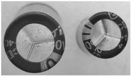
Figure 1-14 Explosion-proof valve of leaded electrolytic capacitor
For small-diameter lead-type electrolytic capacitors, due to the limited volume inside the shell, the gas generated can generally only separate the aluminum shell from the rubber plug. As the diameter of the electrolytic capacitor increases, higher air pressure will be generated during abnormal conditions, which will eject the aluminum casing at high speed, causing danger. Therefore, electrolytic capacitor shells with a diameter greater than or equal to 8mm must be equipped with explosion-proof valves.
Use notches to reduce the strength of the engraved part. When the internal pressure of the electrolytic capacitor exceeds the safe value, the gas inside the electrolytic capacitor shell breaks through the explosion-proof valve, resulting in a convex bottom phenomenon. As shown in Figure 1-15, when the lead-type electrolytic capacitor is powered on When an implosion occurs, the explosion-proof valve of the capacitor is pushed open and is no longer just a convex bottom. It usually explodes at the scratch of the explosion-proof valve, exploding high-pressure gas and part of the electrolyte, which is usually called “explosion”, as shown in Figure 1-16.
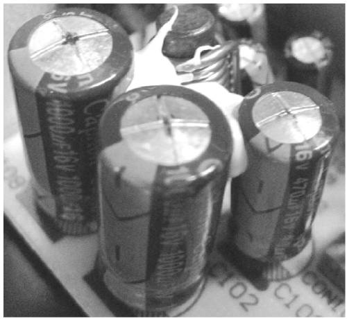
Figure 1-15 The convex bottom phenomenon caused by the increase in internal pressure of leaded electrolytic capacitors
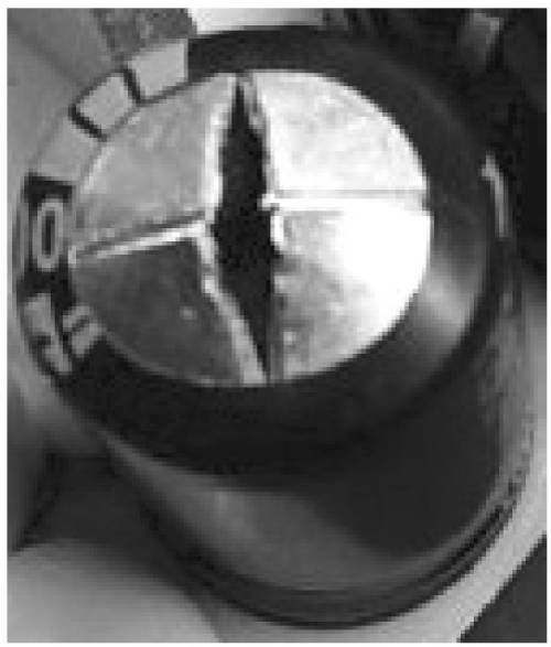
Figure 1-16 Explosion of leaded electrolytic capacitor
The pins of the “horn” type electrolytic capacitor are welded on the circuit board, usually the pins are on the bottom. Therefore, the explosion-proof valve of the “horn” type electrolytic capacitor is similar to the explosion-proof valve of the lead-type electrolytic capacitor, and is set on the top of the aluminum shell, as shown in Figure 1 -17 shown. There are also larger “horn” type electrolytic capacitors that use an explosion-proof valve design with side scratches. The principle is the same as the scratch on the top of the aluminum casing, which will not be described again here.
Bolt-type electrolytic capacitors usually use steel clamps to fix the electrolytic capacitor. The bolts used as electrodes are usually upward, so the explosion-proof valve of the bolt-type electrolytic capacitor is set on the cover plate, as shown in Figure 1-18.
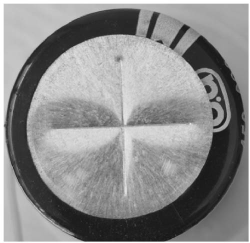
Figure 1-17 Explosion-proof valve of “horn” type electrolytic capacitor
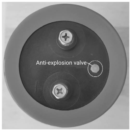
Figure 1-18 Explosion-proof valve of bolt-type electrolytic capacitor
The ultimate pressure of explosion-proof valves for lead-type electrolytic capacitors, “horn” type electrolytic capacitors, and bolt-type electrolytic capacitors is generally set to 0.25MPa, which is about 2.5 atmospheres. “When a horn-type electrolytic capacitor or a bolt-type electrolytic capacitor implodes, the explosion-proof valve is usually opened to release pressure. However, the explosion-proof valve of individual electrolytic capacitors may be defective, causing the explosion-proof valve to explode before the shell can be opened, as shown in Figure 1- 19 shown.
Solid electrolytic capacitors do not have the problem of gas generation, so there is no need to install explosion-proof valves. However, solid electrolytic capacitors can also explode the aluminum casing under extreme conditions. The reason may be that under extreme conditions, since solid electrolytic capacitors do not have the ability to repair the oxide film, once the defects in the positive electrode foil are broken down, they will A short circuit occurs in the solid aluminum electrolytic capacitor. The flow of an extreme overcurrent that is much higher than the ripple current capacity causes extreme heat to vaporize the highly conductive polymer and generate high voltage inside the solid electrolytic capacitor, which is the cause of the explosion of the solid electrolytic capacitor.
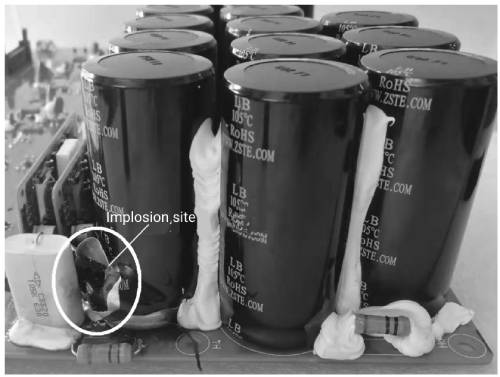
Figure 1-19 Implosion without opening the explosion-proof valve
1.8 Switching power supply enables the rapid development of electrolytic capacitors
Computers are becoming smaller in size and computing power is rapidly increasing, resulting in a significant increase in power consumption. A power supply capable of providing a current capacity of 50A to 100A is required. At this time, the power frequency transformer linear voltage stabilizing circuit is no longer applicable. To solve this problem, the 50Hz power frequency transformer must first be replaced with a transformer above 20kHz, and the voltage stabilization method must also be achieved through PWM switching power conversion.
Before the emergence of switching power supplies, program-controlled switching power supplies used industrial frequency transformers plus thyristor phase-controlled voltage stabilization and current stabilization circuits. Due to the large size of the power frequency transformer and power frequency filter circuit, when the output current of the program-controlled switching power supply exceeds 100A or even 1000A, the power frequency power supply technology requires a high cost to achieve. Using switching power supply solutions can well solve the problems of large size, low efficiency and high cost.
A high-voltage electrolytic capacitor is required in a switching power supply. If it is installed on a circuit board and requires high voltage and large capacitance, a “horn” type electrolytic capacitor is selected, while the output part often uses a lead-type electrolytic capacitor.
The high-voltage electrolytic capacitors required for switching power supplies should be able to withstand much higher ripple currents than early electrolytic capacitors. When selecting electrolytic capacitors, the ripple current may even determine the capacitance of the capacitor. The electrolytic capacitor at the output end needs to consider the ability to filter ripple current and the filtering effect. Capacitance is often not the first factor to consider.
Color TVs are all powered by switching power supplies, and both built-in power supplies and adapters are in switching power supply mode. With the widespread use of computers and monitors, built-in switching power supplies are also required.
Different circuit structures, control modes, and circuit working states affect the working state of electrolytic capacitors and even the life of electrolytic capacitors.
It can be said that the popularization and application of switching power supplies has promoted the development of the electrolytic capacitor industry, and at the same time, the performance of small and medium-sized electrolytic capacitors has been greatly improved.
1.9 Electrolytic capacitors required for power adapter
Electronic devices such as laptop computers, mobile phone chargers, and ubiquitous power adapters are widely used. These applications have a huge demand for electrolytic capacitors, requiring billions of electrolytic capacitors every year. At the same time, increasingly higher requirements are placed on the performance of electrolytic capacitors. Every notebook computer must be equipped with at least one power adapter during its lifetime. The power adapter requires not only high-voltage electrolytic capacitors, but also low-voltage electrolytic capacitors, with more than 100 million used every year. The DC/DC converter and motherboard circuit inside the notebook computer require a large number of electrolytic capacitors, high-frequency low-resistance electrolytic capacitors or solid electrolytic capacitors. The power adapter also includes mobile phone chargers. The annual demand for mobile phone chargers is conservatively estimated at 2 billion. . Mobile phone chargers require not only high-voltage electrolytic capacitors, but also low-voltage electrolytic capacitors. The huge demand for electrolytic capacitors in mobile phone chargers has become a part of the current electrolytic capacitor production capacity that cannot be ignored.
Switching power supply products gave birth to “horn” type electrolytic capacitors, “high frequency low resistance” electrolytic capacitors for output filtering, and even gave birth to solid electrolytic capacitors and laminated electrolytic capacitors. Low-voltage electrolytic capacitors for mobile phone chargers have made solid electrolytic capacitors a reality. Due to the large demand for mobile phone chargers, especially fast chargers, there has even been a special phenomenon that the production capacity of solid electrolytic capacitors cannot keep up with demand.
1.10 Frequency converters, new energy and smart grids strongly promote the development of large electrolytic capacitors
1. Frequency converters give electrolytic capacitors a second chance for rapid development
Since the 1980s, motor speed regulation has gradually been replaced by AC speed regulation from DC motor speed regulation. The most effective method of AC speed regulation is to change the frequency of power supply to the AC motor. However, the frequency of the industrial frequency AC power grid remains unchanged. Frequency converters are mostly used to change the frequency.
With the application of power transistors and insulated gate bipolar transistors, frequency converters have become popular. Large electrolytic capacitors are required in frequency converters. For example, a 15kW frequency converter requires two 3900uF/400V electrolytic capacitors in series. Correspondingly, a 30kW frequency converter requires Four 3900uF/400V electrolytic capacitors are used in two parallel and two series applications. These electrolytic capacitors are large bolt type electrolytic capacitors. Relatively speaking, the production value of ten or dozens of “horn” type electrolytic capacitors can be compared with that of one bolt-type electrolytic capacitor, while lead-type electrolytic capacitors require hundreds or thousands to achieve similar production value.
It can be seen that frequency converters are used more and more, and the huge demand for electrolytic capacitors has led to the development of the large-scale electrolytic capacitor industry.
2. New energy and smart grid
New energy mainly includes wind energy, solar energy, biomass energy, etc. The most common form of utilization of wind energy is wind power generation. High-power wind power generation has high voltage, and film capacitors are mainly used. Due to the limitation of the insulation level of photovoltaic cells, the bus peak voltage does not exceed 1000V, and it is still a 50Hz inverter. Therefore, electrolytic capacitors have become the main capacitors for photovoltaic inverters, especially for single-phase photovoltaic inverters, electrolytic capacitors are the only choice.
The rapid development of electric vehicles has brought new application fields to electrolytic capacitors. First of all, electric vehicle on-board chargers require a large number of high-voltage electrolytic capacitors, at least 450V electrolytic capacitors with a total capacitance of 3000uF. Each single-phase power supply charging pile also requires no less than the electrolytic capacitors of the electric vehicle on-board charger, and high-power charging piles require more high-voltage electrolytic capacitors or film capacitors. Therefore, electric vehicles are a major application area for electrolytic capacitors now and in the future.
My country’s power grid has entered the era of flexible transmission and smart grids, which requires a large number of static var generators (SVG) and active power filters (APF), and the low-voltage side (0.4kV) SVG and APF are High reliability high voltage electrolytic capacitors.
1.11 Electronic lighting gives electrolytic capacitors a third opportunity for rapid development
1. Electrolytic capacitors required for energy-saving lamps
Twenty years ago, energy-saving lamps began to be widely used due to their power saving and ease of use. At their peak, the annual output was billions, which also required billions of electrolytic capacitors. This made energy-saving lamp electrolytic capacitors a highlight of electrolytic capacitors. , many domestic electrolytic capacitor manufacturers started and developed based on energy-saving lamp electrolytic capacitors, and have even become the electrolytic capacitor manufacturer with the highest output value in China.
Due to the special working environment and application characteristics of energy-saving lamps, electrolytic capacitors of energy-saving lamps are required to have the characteristics of high temperature resistance and long life. This demand has promoted the advent of 105°C/10000h and 125°C or even 140°C operating temperature products, which has greatly improved the maximum operating temperature and life of electrolytic capacitors. In China, the electrolytic capacitor with the lowest performance is also 85°C/2000h, which makes the electrolytic capacitor in the switching power supply no longer suffer from short life. It can even be said that as long as the electrolytic capacitor is properly selected, it is no longer the key to the reliability of electronic circuits. Short board.
Another characteristic of electrolytic capacitors for energy-saving lamps is that they must withstand high ripple current and need to provide the ability to provide 3W/uF or even 5W/uF (the output power that can be supported by unit capacitance). The ripple current capability corresponding to unit output power must reach: power frequency ripple current is about 6mAW, high frequency ripple current is about 9mAW, the total effective value converted to 100Hz is about 7.5mA/W, corresponding to 22.5mA/uF, at least 20mA/uF. For electrolytic capacitors, under the performance requirements of ultra-high ripple current, they must also meet the temperature and life requirements of 105°C/10000h. Therefore, whether in terms of output or performance, energy-saving lamp electrolytic capacitors have enabled the rapid development of small high-voltage electrolytic capacitors.
2. Electrolytic capacitors required for LED lighting
In recent years, LED lighting has begun to replace energy-saving lamps. LED bulbs can be directly screwed into E27-type universal lamp sockets and special-type lamp sockets. At the same time, it is hoped that the drive circuit will be as small as possible. Therefore, the aluminum radiator is exposed, and the original aluminum radiator shell driver circuit must be isolated. There are mostly 3 to 10 LED lamp beads (single LEDs), and the current is 0.33A. The output electrolytic capacitor needs to flow through about 400mA ripple current. The output filter capacitor requires a capacitance of more than 220uF, so electrolytic capacitors can only be selected; since the input rectifier is a single-phase power frequency rectification filter, even with power factor correction (PFC), a filter capacitor with a larger capacitance is required, and high-voltage electrolytic Capacitors are bound to be the only option.
If the LED lamp bead and its heat sink can be electrically isolated from the outside world, a more efficient non-isolated driver can be applied. Even so, input rectifier filter electrolytic capacitors and output rectifier filter capacitors are indispensable, and require large capacitance.
In order to simplify the drive circuit, if the circuit design is reasonable, a linear drive circuit can even be used, but a rectifier filter electrolytic capacitor is still required, but only a high-voltage electrolytic capacitor is required. A capacitor step-down drive circuit can also be used, which also requires an electrolytic capacitor.
LED lighting has almost replaced fluorescent/book lamp lighting and incandescent lighting, and has also partially replaced high-intensity discharge (HID) lighting. Therefore, the market requires billions of LED drivers every year, which also requires billions of electrolytic capacitors.
Since most LED drivers work in harsh environments, mainly high temperature environments, this requires electrolytic capacitors to not only be small in size, but also to be able to work for a long time under high temperature and high ripple current conditions. Therefore, the performance of high-voltage electrolytic capacitors has been improved again based on the electrolytic capacitors of energy-saving lamps.
In order to reduce the cost of LED drivers, LED driver manufacturers have put forward higher technical requirements for high-voltage electrolytic capacitors, but these requirements cannot be met by electrolytic capacitor manufacturers. Perhaps in the not-too-distant future, our country will overcome this difficulty and be at the forefront of the world just like it did with electrolytic capacitors for energy-saving lamps.
1.12 Mobile phone chargers promote the development of solid electrolytic capacitors
1. Application issues of electrolytic capacitors
1) Compared with other capacitors, the traditional concept is that electrolytic capacitors have a short life. Now the electrolytic capacitor with the longest life can reach 105°C/16000h, which is quite different from the 100000h claimed by film capacitors.
2) The equivalent series resistance is large, resulting in a limited ripple current that the electrolytic capacitor can withstand, so it has to choose to increase the capacitance to meet the application.
The first problem no longer restricts electrolytic capacitors in practical applications, while the second problem is becoming more and more serious. For users, are there any other dielectric capacitors that can replace it? In fact, there are almost none! Low-voltage, large-capacity film capacitors are very large and expensive. Ceramic capacitors with good performance are difficult to achieve more than 100uF; electrolytic capacitors also have streaks. The problem of insufficient wave current capability and high price. In fact, the biggest problem with electrolytic capacitors is that the conductivity of the electrolyte is low. If the conductivity can be increased by one or even two orders of magnitude, the ability of the electrolytic capacitor to withstand ripple current will increase exponentially.
Solid electrolytic capacitors made of high-conductivity polymer conductive polymers instead of conventional electrolytes can obtain high ripple current capabilities. For example, a 330uF/16V solid electrolytic capacitor has a ripple current capability of close to 5A, while high-voltage capacitors with the same specifications have high ripple current capabilities. The ripple current capability of low-frequency electrolytic capacitors will not exceed 0.4A! The huge ripple current capability benefits from the ultra-low Equivalent Series Resistance (ESR). For example, the ESR of the 330uF/16V solid electrolytic capacitor is the largest The value is 10mQ, and the ripple current capability is 7.7A (quoted from the ZE series data of Changzhou Zhouyu Electronics). Even the best high-frequency low-resistance electrolytic capacitors with the same specification have an ESR of 0.22Q, and the ripple current capability is 0.4A (quoted from RUBY-CON’s YXJ series data).
2. Reasons for the application demand of solid electrolytic capacitors
In the mid-to-late 1980s, desktop computers entered the Pentium era. The CPU frequency quickly rose from MHz to above GH, and the CPU current also climbed to tens of amps. The corresponding ripple current in the motherboard power supply bypass capacitor rose to 2A or even higher. At the same time, the power supply bypass capacitor current of desktop computer graphics cards also exceeds 1A, which makes ordinary electrolytic capacitors unable to adapt. Although high-frequency low-resistance electrolytic capacitors later appeared, the ripple current and temperature are still It appears to be inadequate, leading to its early failure. For example, the Dell computer motherboard electrolytic capacitor exploded. Many computers even became stuck and could not work after being used for several years. However, they could recover after replacing the motherboard electrolytic capacitor. You can also connect two 10uF MLCCs in parallel to each electrolytic capacitor. (laminated ceramic capacitors) will do.
Solid electrolytic capacitors came into being under this application demand. Judging from the previous data, solid electrolytic capacitors can withstand ripple current 10 times that of high-frequency low-resistance electrolytic capacitors, which can well solve the power supply bypass problem in high-frequency, high-ripple current applications such as computer motherboards and graphics cards.
With the localization of solid electrolytic capacitors, their price is only about three times that of high-frequency low-resistance electrolytic capacitors of the same specifications, making them highly competitive in practical applications.
3. Extended applications of solid electrolytic capacitors
If solid electrolytic capacitors were only used in the computer field, their application volume would not be large and their prices would not drop to today’s levels.
The large number of applications of fourth-generation smartphones requires a large number of chargers. The batteries of fourth-generation mobile phones are significantly larger than those of second- and third-generation mobile phones. The charging current increases from 0.3~0.5A to 2A, and fast chargers can even reach 4A! The ripple current flowing through the corresponding charger output filter capacitor rises from about 0.5A for second- and third-generation mobile phone chargers to 1.2A, 2.4A for fourth-generation smartphones, or 4.8A for fast chargers. Even at 1.2A, a 1000uF/10V electrolytic capacitor is in an overcurrent state, especially the electrolytic capacitor in a mobile phone charger. To make the size of the mobile phone charger as small as possible, the output electrolytic capacitor needs to be as small as possible. It is absolutely impossible to achieve a liquid electrolytic capacitor that can withstand 2.5A ripple current.
Since the carbon foil negative electrode of the solid electrolytic capacitor has a very high specific volume, the volume of the solid aluminum electrolytic capacitor is significantly reduced, even smaller than that of a liquid aluminum electrolytic capacitor with the same rated voltage and capacitance. Therefore, it has become one of the reasons why the size of mobile phone chargers has been greatly reduced while ensuring performance.
In the 4A output state, two 820uF/10V solid electrolytic capacitors connected in parallel can withstand a ripple current of 12A.
In fact, a solid electrolytic capacitor can meet the output current of a mobile phone charger of 2A, but a high-frequency low-resistance electrolytic capacitor is unimaginable. Solid electrolytic capacitors can also be used in switching power supplies. A more extreme case is to replace all low-voltage, high-frequency, low-resistance electrolytic capacitors with solid electrolytic capacitors, and use 1/3 of the capacitance of high-frequency, low-resistance electrolytic capacitors to maintain the same cost as high-frequency, low-resistance electrolytic capacitors and obtain better performance. For filtering characteristics, if you are more conservative, you can use solid electrolytic capacitors to replace general high-frequency low-resistance electrolytic capacitors to simplify loop compensation. The cost is the same, but the performance obtained is better than using all high-frequency, low-resistance electrolytic capacitors.
In communication equipment, many circuit board units not only require a relatively large power supply current, but also the ripple current generated by the load is very large. If only ceramic capacitors are used, the capacitance is insufficient. If only high-frequency, low-resistance electrolytic capacitors are used, the ripple current capability Obviously insufficient, the use of solid electrolytic capacitors can solve this problem well.
As the ripple current generated by electronic circuits becomes larger and larger, high-ripple current power supply bypass rectification and filtering becomes inevitable. Solid electrolytic capacitors will be one of the best choices.
1.13 Innovative manufacturing processes lead to improvement of electrolytic capacitor performance
1. Electrolytic capacitors move from information electronics technology to power electronics technology
Power electronics technology has gone through the era of radio and industrial electronics of electron tubes, the era of inverter units, the era of classic power electronics technology of thyristors, the era of modern power electronics technology marked by switching power supplies, and the upcoming era of wide bandgap power semiconductor devices. The era of radio frequency power electronics technology.
In the radio era, electrolytic capacitors were packaged in paper tubes to adapt to cheap requirements and the lack of aluminum resources. From the current perspective, this kind of package is of a large size, but it can adapt to the application requirements of large-volume tube circuits. In the era of transistors, since the volume of transistors is much smaller than that of electron tubes, there is also a demand for small volumes of other electronic components. , electrolytic capacitors are no exception, so small-volume electrolytic capacitors emerged as the times require; for high-power converters such as AC units and thyristors, electrolytic capacitors seem to have no connection, so there is no demand for high-voltage large-capacity electrolytic capacitors during this period.
The advent of switching power supply marks that power electronics technology has entered the era of modern power electronics technology. Electric energy conversion no longer relies on converter units, tube converters, and thyristor converters. Because power semiconductor devices no longer rely only on the positive electrode like thyristors and diodes. Instead of reverse voltage shutdown, the control pole signal can be used to shut down, which fundamentally changes the control mode and working state of the power electronic circuit, from a current source power converter to a voltage source power converter, and can be used anytime and anywhere. Turn off power semiconductor devices. At this time, the DC bus needs to have good “full-band” low impedance characteristics, but the DC power supply does not have this characteristic and requires a capacitor with a larger capacitance in parallel with the DC bus. For example, variable frequency air conditioners, televisions, frequency converters, inverter arc welding power supplies, photovoltaic inverters, motor drives, electric vehicle on-board chargers, charging piles, smart grid SVG, etc. require medium and large electrolytic capacitors, and even electronic lighting also requires a large number of of electrolytic capacitors
The modern era of power electronics technology requires electrolytic capacitors that can withstand increasingly higher effective current values, good high-frequency characteristics, smaller size, longer life and higher operating temperatures. Today’s electrolytic capacitors seem to meet the performance requirements of current power electronic circuits for electrolytic capacitors.
2. Radio frequency power electronics technology puts forward higher requirements for electrolytic capacitors
With the practical application of wide bandgap power semiconductor devices, the switching frequency of power electronic circuits must be increased by at least one order of magnitude. Small and medium-sized electrolytic capacitors need to meet the switching frequency of 500kHz and have good low impedance characteristics at 1MHz. Electrolytic capacitors are required to not only With higher current withstand capability and small size, the most critical thing is to try to reduce the parasitic inductance of electrolytic capacitors, and to reduce it by one or even two orders of magnitude, the existing manufacturing method will no longer meet the requirements. If electrolytic capacitors cannot meet this technical requirement, electrolytic capacitors will be in a position to assist other capacitors in the field of radio frequency power electronics technology.
Electrolytic capacitors used in radio frequency power electronics technology are not only smaller electrolytic capacitors, but also electrolytic capacitors with lower parasitic inductance, can withstand higher ripple current, and can withstand higher temperatures.
3. The future of electrolytic capacitors
The development of electrolytic capacitors will also follow the Olympic motto “Faster, higher, stronger. Faster means having lower parasitic inductance, higher means having higher current withstand capability, and stronger means adapting to various harsh conditions. Impact of working conditions.
For example, current solid aluminum electrolytic capacitors can increase the current resistance per unit capacitance of electrolytic capacitors with the same voltage by one to two orders of magnitude. The central part of the electrolytic capacitor is forced to cool through the negative electrode extension to improve the current resistance; through the laminated The manufacturing technology eliminates the inherent winding parasitic inductance of the winding type, leaving only the parasitic inductance of the physical length; through two or even multiple impregnations and aging, the inherent flaws of poor aging of liquid electrolytic capacitors can be basically eliminated. In the future, we can even learn from the theory of feedthrough capacitors. To realize “through-core electrolytic capacitors” and further weaken the parasitic inductance due to physical length, we can learn from the non-inductive manufacturing technology of film capacitors to achieve the “inductive” nature of the rolled core; the core after being nailed and rolled is processed into a positive electrode” “formed” and then impregnated with electrolyte, which greatly reduces the gas production during the aging process and the convex bottom or even implosion caused by leakage current due to poor aging. This is beneficial to improving the reliability and operating life of electrolytic capacitors and greatly reducing the failure rate of electrolytic capacitors. If we can manage to increase the specific capacity of electrolytic capacitors by an order of magnitude, we can realize high-voltage (such as 400V or even higher) super aluminum electrolytic capacitors to replace the existing double-layer supercapacitors with a withstand voltage of only 2.7V, greatly improving supercapacitors. reliability and operating life. One day, “battery-level” supercapacitors with energy densities reaching or exceeding 100W·h/kg may replace most existing power batteries, because the reliability of the energy storage system will be greatly improved without the need for a large number of series connections!