1 Lead-pin electrolytic capacitor-electrolytic capacitor data that keeps pace with the times
Lead pin electrolytic capacitor —To use electrolytic capacitors well, you must understand the data of electrolytic capacitors, and the data of electrolytic capacitors reflects the manufacturer’s understanding of electrolytic capacitors and the user’s application scenarios.
The data of lead-pin electrolytic capacitors also keep pace with the times. Initially, the data for electrolytic capacitors in vacuum tube circuits only included rated voltage, capacitance, capacitance tolerance, loss factor, leakage current and dimensions. In those days rectifier diodes were electron tubes with high “on” resistance. Compared with the current application status of integrated circuits, vacuum tube circuits are in a high-voltage and low-current state, and the “ripple current” generated is also very small. At the same time, due to the large size of the vacuum tube circuit, there is no strict limit on the size of the electrolytic capacitor.
Even in the era of transistors, there are no special requirements for electrolytic capacitor data, only the size is reduced. Such electrolytic capacitor data only requires one page of 32 pages to put down.
The first real advancement in electrolytic capacitor data came from the switching of computer power supplies. At this time, electrolytic capacitors are required to have a maximum working environment temperature of 85°C, and there are also life requirements – 1000h becomes the bottom line.
The beginning of the computer age gave electrolytic capacitors a maximum operating temperature and lifespan. Electrolytic capacitors were also required to provide data on ripple current withstand capabilities, and then there were ESR data requirements.
These newly added data are reflected on the first page of the data table.
Due to different storage conditions and usage conditions, some electrolytic capacitor data also include storage life parameters at high temperature without bias voltage.
With the widespread application of switching power supplies and frequency converters, more detailed requirements have been put forward for the life of electrolytic capacitors. So in the data sheet of the electrolytic capacitor, the curves of life, temperature, and ripple current appear.
Electrolytic capacitors are widely used in power electronic circuits, and their working conditions are different, which puts forward requirements for the impedance frequency characteristics and ESR frequency characteristics of electrolytic capacitors, so the impedance frequency characteristics and ESR frequency characteristic curves of electrolytic capacitors appeared.
Based on the above two curve families, the temperature conversion coefficient and frequency conversion coefficient of the electrolytic capacitor ripple current are derived, making the data of electrolytic capacitors more complete.
With the “deep cultivation” of power electronic circuits and the widespread application requirements of high-speed switching power semiconductor devices (such as MOSFETs and IGBTs), electrolytic capacitors as DC bus capacitors should provide equivalent series inductance data.
Since the ripple current flowing through the electrolytic capacitor causes heating of the electrolytic capacitor, especially large currents will cause significant heating, the thermal resistance of electrolytic capacitors with various sizes of shells is also integrated into the electrolytic capacitor data sheet. Different electrolytic capacitor manufacturers will give data or curves that they think are appropriate. The more comprehensive the data or curves are, the smoother the application will be and the better the performance of the electrolytic capacitor will be exerted. For power electronics engineers with rich design experience, the more comprehensive the data provided by component manufacturers, the better.
Guide pin electrolytic capacitor-the above is the data analysis of electrolytic capacitors that keeps pace with the times
2 Lead pin type electrolytic capacitor CD03 series data
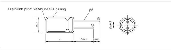
The appearance of CD03 series general-purpose aluminum electrolytic capacitors is shown in Figure 1-1.
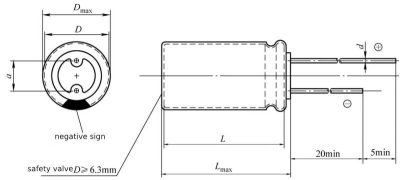
Figure 1-1 Outline diagram of CD03 series general-purpose aluminum electrolytic capacitors
The technical data of CD03 series aluminum electrolytic capacitors are shown in Table 1-1 and Table 1-2.
Table 1-1 Performance overview of CD03 series aluminum electrolytic capacitors
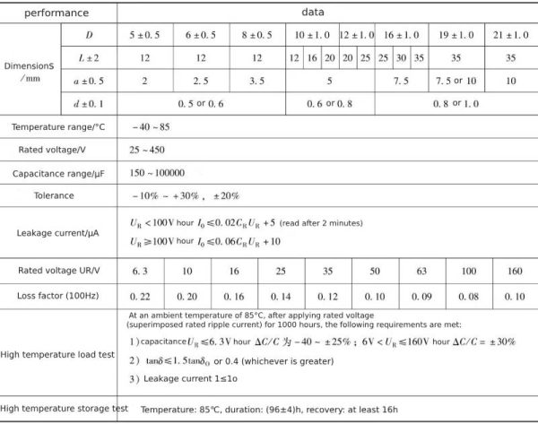
Table 1-2 Electrical parameters of CD03 (CD11) series aluminum electrolytic capacitors
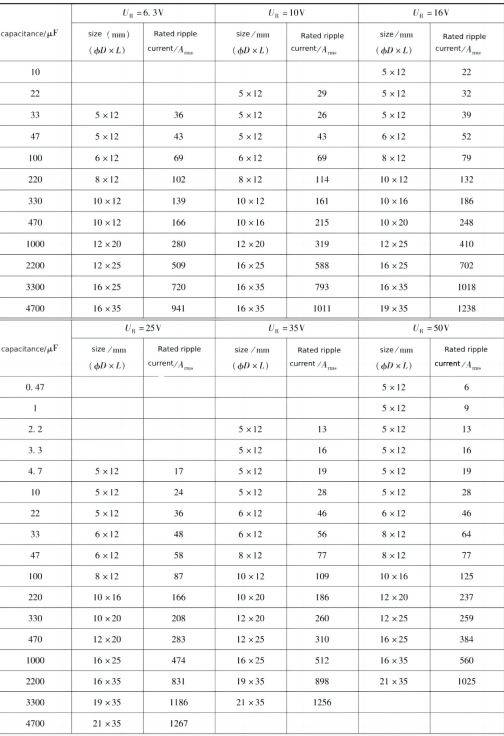 Continued
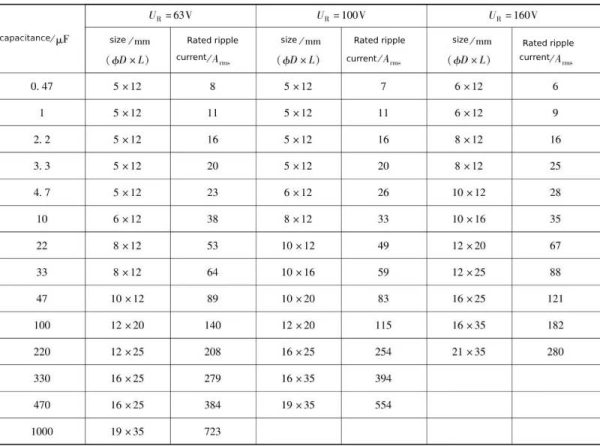
The rated ripple current test conditions in Table 1-2 are 85°C, 100Hz. Table 1-1 and Table 1-2 are data given in the late 1990s, so they contain ripple current data. After deducting the ripple current, high-temperature load test and high-temperature storage test data, the data given in Table 1-1 and Table 1-2 are closest to the early electrolytic capacitor data.
The CD03 series is an 85℃/1000h product, which is the lowest grade of ethylene glycol electrolytic capacitors. As the application fields of electronic circuits become more and more extensive, there are new requirements for the size of electrolytic capacitors. National standard CD110 has become a general-purpose electrolytic capacitor replacing CD03. The CD03 series has withdrawn from the Chinese electrolytic capacitor market and become history. The fundamental reason is that its performance is far from suitable for today’s low-end applications.
3 Lead pin electrolytic capacitor CD110 series data
CD110 series electrolytic capacitors are upgraded models of CD03 lead-pin electrolytic capacitors. The improved features include: lifespan increased from 1000h of CD03 to 2000h; volume reduced, and the shell size of each specification reduced by at least one size; ripple current increased . The CD110 data in the 2021 Jianghai capacitor sample also adds the temperature conversion coefficient, frequency conversion coefficient, ESR under 120Hz conditions of ripple current, and the curves of life, temperature, and ripple current. Compared with the data of this series of electrolytic capacitors and the data of new electrolytic capacitors, except for the difference in specific data values, there is basically no difference in the data items.
The data of CD110 series aluminum electrolytic capacitors are shown in Table 1-3 ~ Table 1-8.
Brief description: The maximum operating (ambient) temperature is 85°C, the load life is 2000h under the ambient temperature of 85°C, small size, low cost, suitable for general consumer electronics.
Table 1-3 Performance overview of CD110 series aluminum electrolytic capacitors
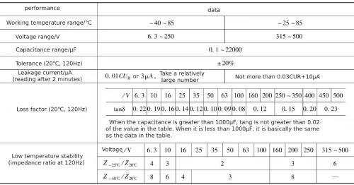
Table 1-4 Life span
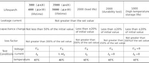
Note: After completing the high temperature test, apply UR to the capacitor for 30min and test after 24h.
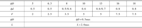
Table 1-5 Appearance and dimensions (unit: mm)
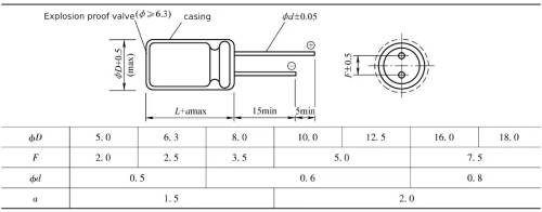 Table 1-6 Frequency conversion coefficient of ripple current
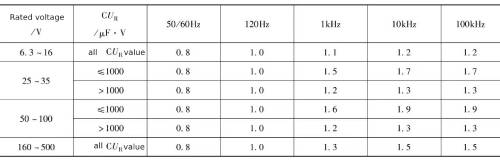 Table 1-7 Temperature conversion coefficient of ripple current
![]()
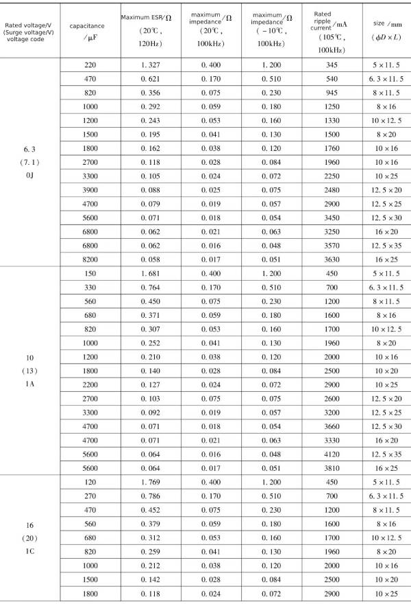
Table 1-8 Gas parameters of CD110 series aluminum-aluminum electrolytic capacitors
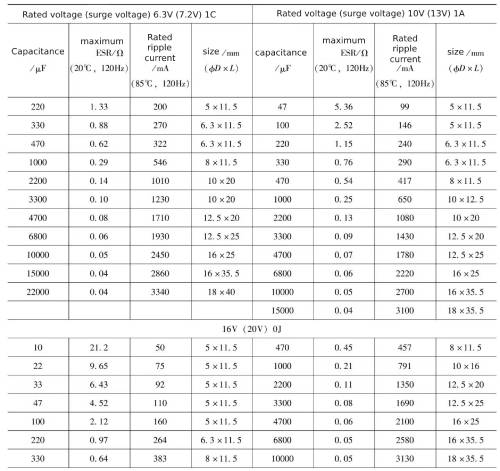 Continued
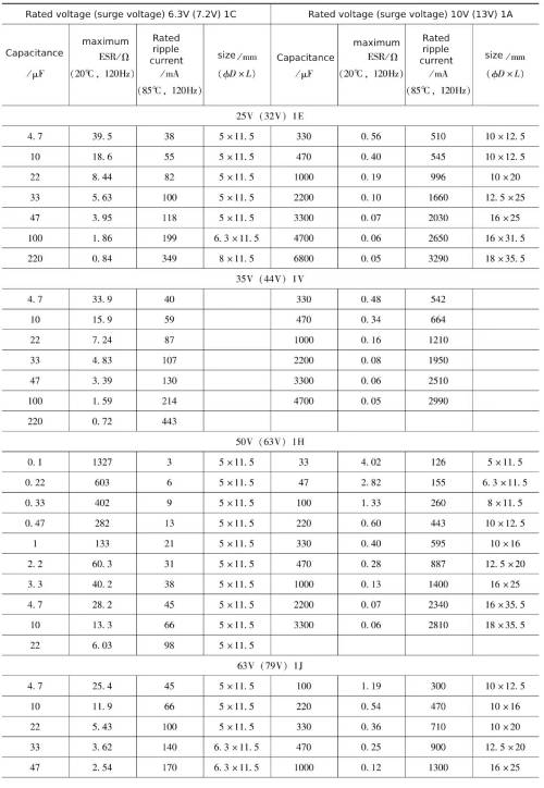 Continued
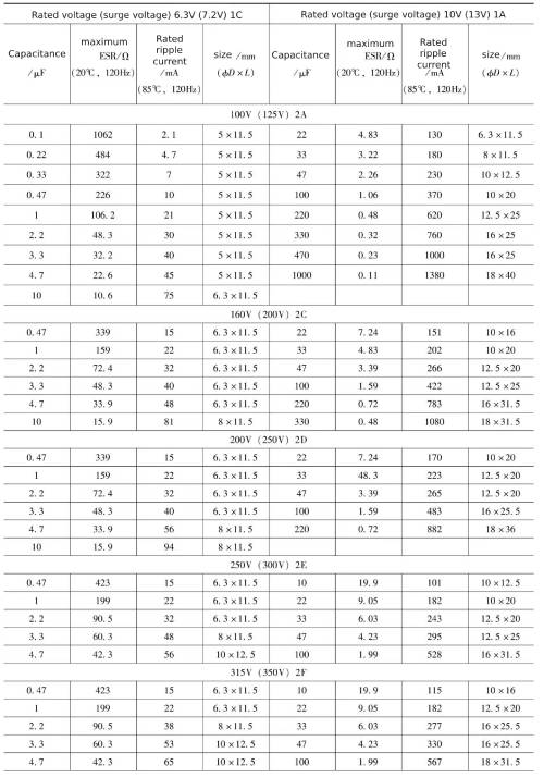 Continued
CD110 series aluminum electrolytic capacitors are general-purpose electrolytic capacitors with the lowest performance requirements in China. They are characterized by low price (less than 1/2 the price of high-frequency low-resistance aluminum electrolytic capacitors) and can meet performance requirements in applications with low requirements.
The relationship between CD110 series electrolytic capacitor life, temperature and ripple current is shown in Figure 1-2.
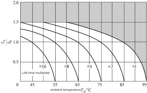 Figure 1-2 Relationship between life, temperature, and ripple current
4 Lead pin electrolytic capacitor CD285 series data
CD285 series electrolytic capacitors are high-frequency low-resistance lead-pin electrolytic capacitors. They are low-voltage electrolytic capacitor products with a service life of 105°C and 6000-10000h. They have the lowest ESR and the highest ripple current among high-frequency low-resistance aluminum electrolytic capacitors. models.
The data of CD285 series aluminum electrolytic capacitors are shown in Table 1-9 ~ Table 1-14.
Table 1-9 Performance overview of CD285 series aluminum electrolytic capacitors
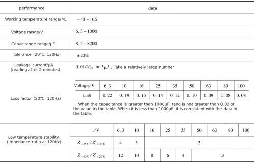
Table 1-10 Lifespan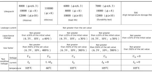
Note: Lead pin electrolytic capacitor—After completing the high temperature test, apply UR to the capacitor for 30min and test after 24h.
Table 1-11 Appearance and dimensions (unit: mm)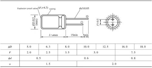 Table 1-12 Frequency conversion coefficient
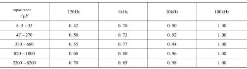 Table 1-13 Temperature conversion coefficient
![]() Table 1-14 Electrical parameters of CD285 series aluminum electrolytic capacitors
Table 1-14 Electrical parameters of CD285 series aluminum electrolytic capacitors
 Continued
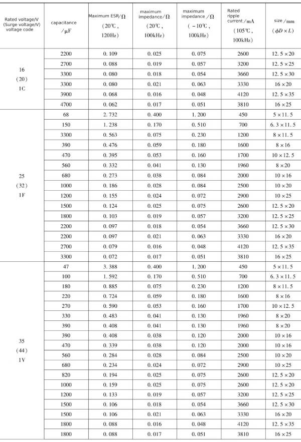 Continued
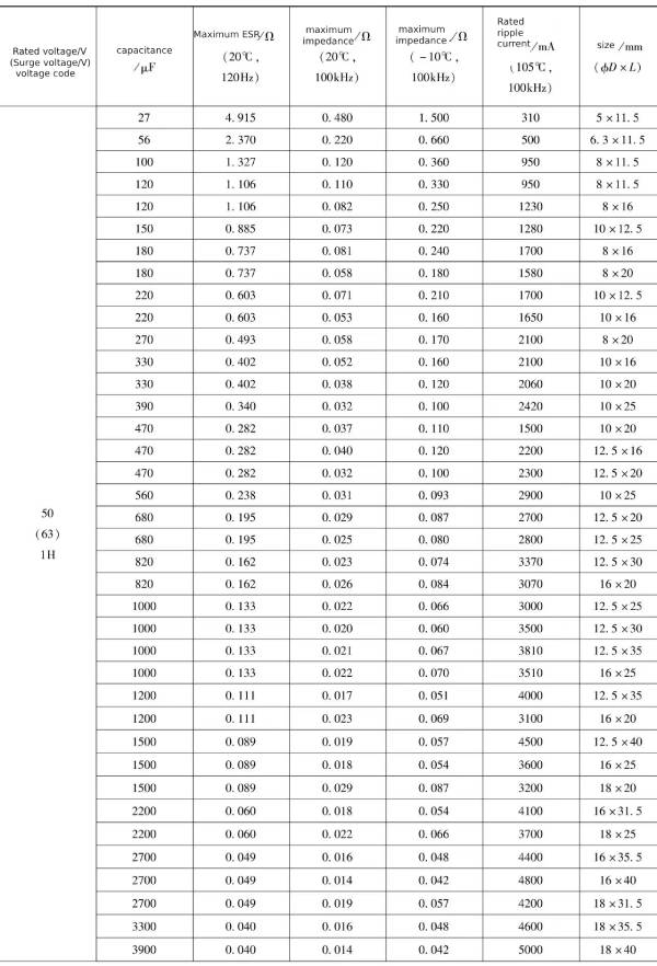 Continued
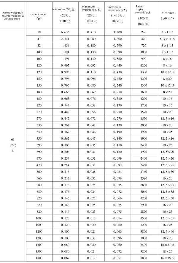 Continued
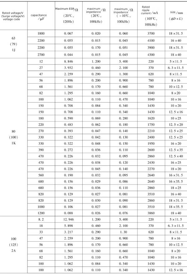 Continued
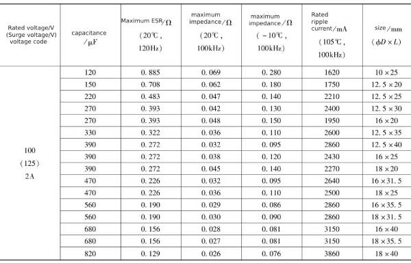 The relationship between CD285 series aluminum electrolytic capacitor life, temperature and ripple current is shown in Figure 1-3.
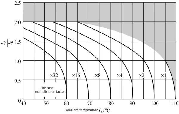 Figure 1-3 Relationship between life, temperature, and ripple current
5 CD26 HS series slim electrolytic capacitor data
Some electronic circuits, such as LED-backlit flat-panel TVs, require that the height of the circuit board plus components should not be higher than 13.8mm. If the thickness of the circuit board (about 1.5mm) and the height of the soldering pins (about 1.5~2.5mm) are deducted, the safety space is not considered ( About 3mm), the height requirement of components shall not be higher than 10mm. For 100~220μF/450V electrolytic capacitors, it is almost impossible to make them “short and fat” with a height of less than 8mm. Therefore, it is necessary to make slender electrolytic capacitors and place them on the circuit board when using them to minimize the Reduce the overall height of the circuit board, and even use multiple parallel connections to meet capacitance requirements.
The data of CD26 HS series aluminum electrolytic capacitors are shown in Table 1-5 ~ Table 1-20.
Table 1-15 Performance overview of CD26HS series aluminum electrolytic capacitors
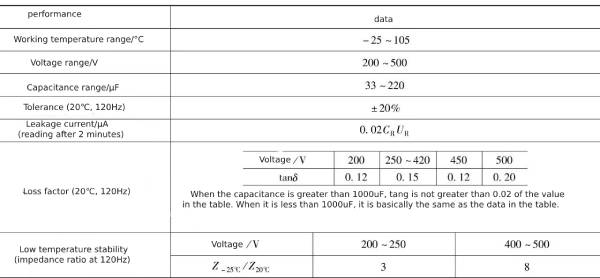
Table 1-16 Lifespan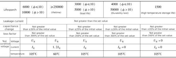
Note: Lead pin electrolytic capacitor—After completing the high temperature test, apply UR to the capacitor for 30min and test after 24h.
Table 1-17 Appearance and dimensions (unit: mm)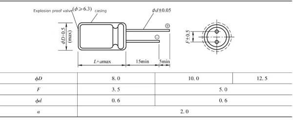 Table 1-18 Frequency conversion coefficient of ripple wave
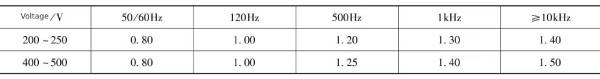 Table 1-19 Temperature conversion coefficient of ripple current
 Table 1-20 Electrical parameters of CD26HS series aluminum electrolytic capacitors
 Continued
 The relationship between CD26 HS series aluminum electrolytic capacitor life, temperature and ripple current is shown in Figure 1-4.
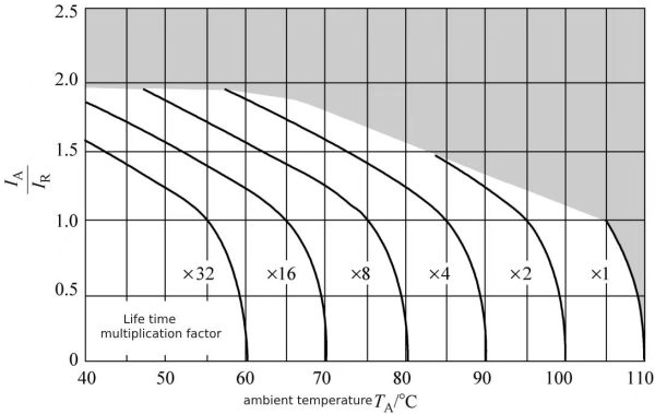 Figure 1-4 Relationship between life, temperature, and ripple current
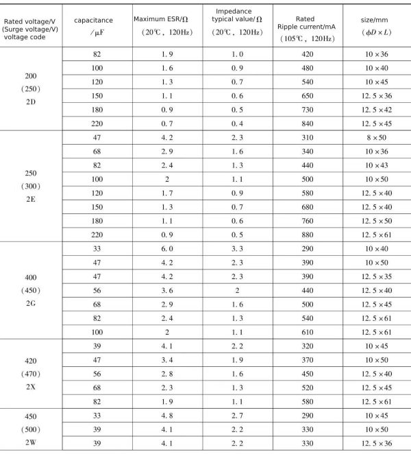
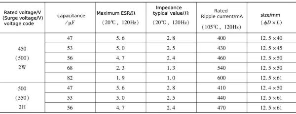
6 Domestic small high voltage, high temperature, long life electrolytic capacitor CD11 GA series data
In electronic lighting and power adapter applications, electrolytic capacitors need to have a long enough life, especially high-voltage aluminum electrolytic capacitors. Because it is a closed space, the ambient temperature of electrolytic capacitors is very high, and high-temperature resistant aluminum electrolytic capacitors are required, such as 105℃/10000h or 125~130℃/2000~5000h. This section takes the CD11 GA high-temperature electrolytic capacitor as an example.
The performance summary of CD11 GA high temperature electrolytic capacitor is shown in Table 1-21.
Table 1-21 Performance overview of CD11GA high temperature electrolytic capacitor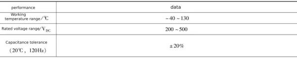 Continued
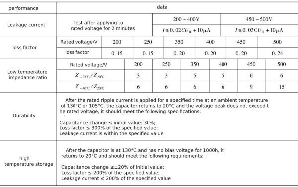
The relationship between life and size is shown in Table 1-22
Table 1-22 Relationship between life and size

The ripple current frequency conversion coefficient is shown in Table 1-23.
Table 1-23 Ripple current frequency conversion coefficient
The appearance and dimensions of CD11 GA are shown in Table 1-24.
Table 1-24 CD11GA appearance and dimensions (unit: mm)
 Continued
Electrical parameter table 1-25
Table 1-25 Electrical parameters of CD11GA series aluminum electrolytic capacitors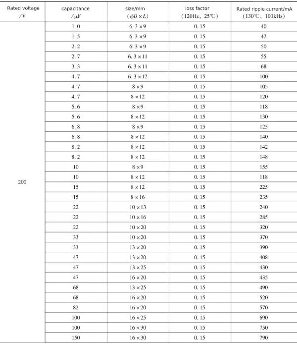 Continued
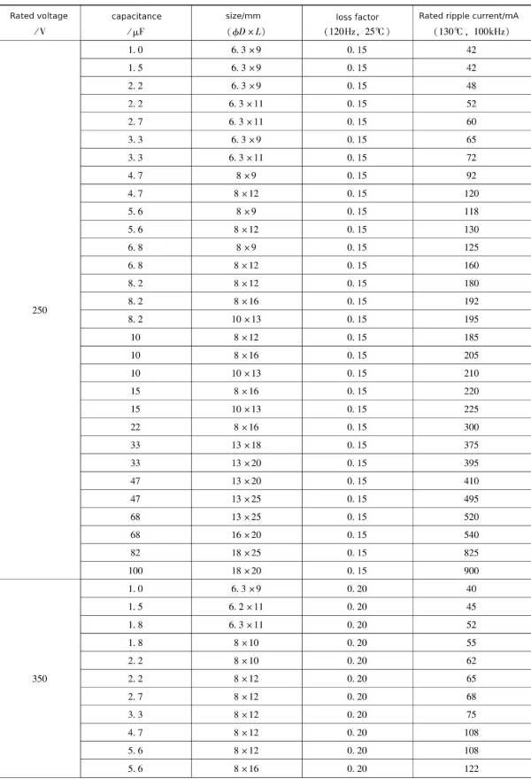 Continued
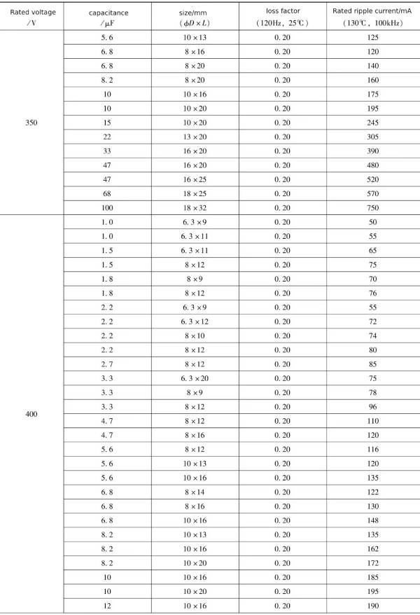 Continued
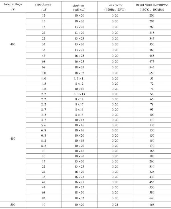
7 Lead pin type electrolytic capacitor bent legs
7.1 Requirements for pin bending of lead-pin electrolytic capacitors
Lead-pin electrolytic capacitors can not only be directly plugged into the circuit board, but can also be installed horizontally on the circuit board. The pin spacing of small-diameter high-voltage electrolytic capacitors is relatively small, and assembly on the circuit board may cause the circuit board pad spacing to be too small. If the insulation requirements cannot be met, the electrolytic capacitor pin spacing can be expanded to adapt to the insulation distance requirements on the circuit board.
When the lead-pin electrolytic capacitor is placed horizontally on the circuit board, the leads of the electrolytic capacitor need to be bent to insert into the corresponding pad. According to the bending direction, they are divided into right bend and left bend. The bent pins are bent according to the correct direction. The negative electrode is divided into long curved leg and short curved leg.
In order to limit the insertion position of the lead-pin electrolytic capacitor, it is necessary to bend the pins into a “K” shape or fix the electrolytic capacitor on the pad so that it will not fall off before soldering.
Surface mount electronic components are increasingly used, and many of the original plug-in electronic components are gradually changed to surface mount. The corresponding electrolytic capacitors have also entered the surface mount era. Surface mount electrolytic capacitors can be simply understood as assembling lead-pin electrolytic capacitors on a special surface mount base.
Surface mount electrolytic capacitors are increasingly in demand in cheap electronics, but electrolytic capacitors with surface mount bases cost nearly 40% more than lead-pin electrolytic capacitors. If electrolytic capacitors without surface mount bases can be realized, the cost of surface mount electrolytic capacitors will undoubtedly be significantly reduced. As a result, the bent-leg surface-mount electrolytic capacitor package form came out and replaced many surface-mount electrolytic capacitors with bases in the field of medium and high-voltage electrolytic capacitors.
From the perspective of reliability, electrolytic capacitors should not be bent directly by hand. Doing so will cause damage to the core due to external forces. If it is a prototype test, you need to use tools to clamp the roots of the electrolytic capacitor pins and then bend them manually; if it is mass production, the best solution is for the electrolytic capacitor manufacturer to directly bend and cut the electrolytic capacitor pins according to customer requirements. foot.
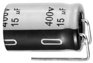
Figure 1-5 L-shaped lead pin bent leg chip electrolytic capacitor
7.2 Surface mount bending form
Surface mount bent leg forms can be L-shaped, T-shaped, M-shaped, or Z-shaped.
The L-shaped lead pin bent leg chip electrolytic capacitor is shown in Figure 1-5, and its appearance is shown in Figure 1-6.
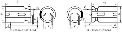
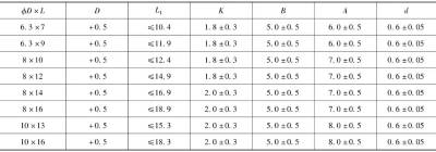
Figure 1-6 Appearance of L-shaped lead pin bent leg chip electrolytic capacitor
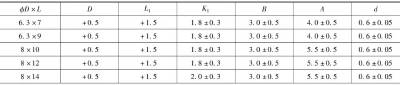
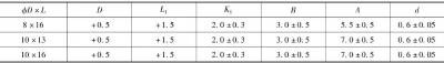
The L-shaped lead pin bent leg chip electrolytic capacitor has a diameter of 6.3~10mm and a length of 9~20mm, see Table 1-26. The 20mm length is significantly longer than the chip electrolytic capacitor with a surface mount base (10×10mm).
Table 1-26 Dimensions of L-shaped lead pin bent leg chip electrolytic capacitor (unit: mm)
 Continued
The T-shaped lead pin bent leg chip electrolytic capacitor is shown in Figure 1-7, the appearance is shown in Figure 1-8, and the overall dimensions are shown in Table 1-27.
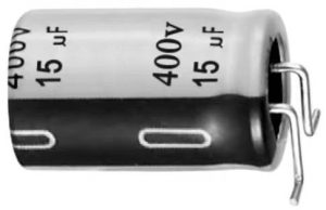 Figure 1-7 T-shaped lead pin bent leg chip electrolytic capacitor
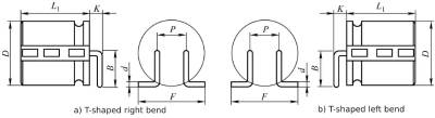
Figure 1-8 Appearance of T-shaped lead pin bent leg chip electrolytic capacitor
Table 1-27 Dimensions of T-shaped lead pin bent leg electrolytic capacitor (unit: mm)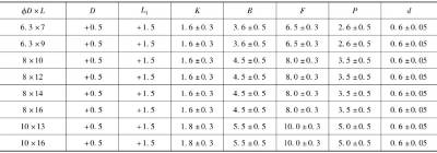
The M-shaped lead-pin bent-leg chip electrolytic capacitor is shown in Figure 1-9, and its appearance is shown in Figure 1-10.
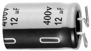 Figure 1-9 M type lead pin bent leg chip electrolytic capacitor
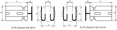
Figure 1-10 Appearance of M-type lead pin bent leg chip electrolytic capacitor
By slightly modifying the shape of the M-shaped lead pin bent leg, you can obtain a C-shaped lead pin bent leg chip electrolytic capacitor. The appearance is shown in Figure 1-11, and the overall dimensions are shown in Table 1-28.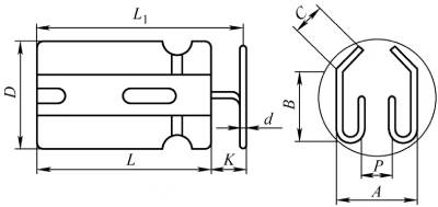
Figure 1-11 Appearance of C-shaped lead pin bent leg chip electrolytic capacitor
Table 1-28 Dimensions of C-type lead pin bent leg chip electrolytic capacitor (unit: mm)
 The Z-type lead pin bent leg chip electrolytic capacitor is shown in Figure 1-12, and its appearance is shown in Figure 1-13.
 Figure 1-12 Z-shaped lead pin bent leg chip electrolytic capacitor
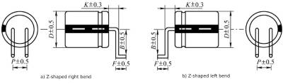 Figure 1-13 Appearance of Z-shaped lead pin bent leg chip electrolytic capacitor
7.3 Horizontal installation method with bent legs
Guide pin electrolytic capacitors can be installed vertically or horizontally using plug-in methods. Horizontal installation requires bending the pins. The simplest is straight leg bending, and different manufacturers give different markings, as shown in Figure 1-14. In order to suit the different assembly directions of the circuit board, the horizontal bent legs need to be divided into right and left bends.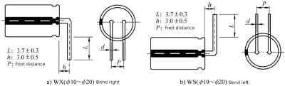
Figure 1-14 Appearance of plug-in bent leg chip electrolytic capacitor
The bent leg form can also adopt the outer “K” bent leg method, as shown in Figure 1-15.
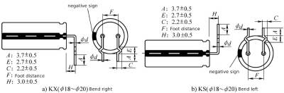
Figure 1-15 Appearance of plug-in external K-shaped leg chip electrolytic capacitor
Small diameter electrolytic capacitors have smaller pitches, such as 2.5mm or 3.5mm. In order to meet the creepage distance requirements of the circuit board, the foot spacing needs to be enlarged. Figure 1-16 shows the bent foot method of extending the pins outward.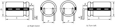 Figure 1-16 Appearance of plug-in type externally expanded bent leg chip electrolytic capacitor
In order to facilitate circuit board wiring, electrolytic capacitors with bent legs can also be staggered with positive and negative electrodes, usually with short negative poles and bent legs, as shown in Figure 1-17.
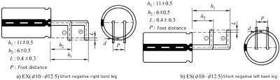 Figure 1-17 Appearance of short negative bent leg chip electrolytic capacitor
7.4 Curved legs for upright installation
There are also various ways of bending the legs for upright assembly.
The pins of small-diameter electrolytic capacitors installed vertically can also use the outward-expanding bent leg method, while some large-diameter electrolytic capacitors use the inward-bending leg method.
Electrolytic capacitors with externally expanded pins or internally contracted pins are shown in Figure 1-18 and Figure 1-19.
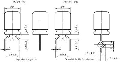 Figure 1-18 Expanded cutouts of small-diameter electrolytic capacitors
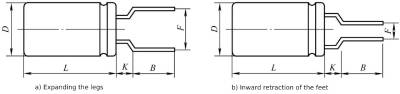 Figure 1-19 Expanding and retracting legs of lead-pin electrolytic capacitors
Even if there is no need for external expansion and internal contraction, the lead pin electrolytic capacitor can be cut according to user needs, such as internal K cutting and external K cutting, straight cutting, and double K cutting.
Figure 1-20 and Figure 1-21 respectively show the plug-in type inner K-cut pins, outer K-cut pins and straight pin cut method.
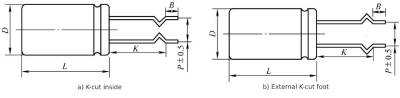 Figure 1-20 Inner K-cut pin and outer K-cut pin of plug-in electrolytic capacitor
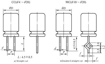 Figure 1-21 Straight-cut series of plug-in electrolytic capacitors
Summarize:
Lead-pin electrolytic capacitor—Mainly detect the actual data of CD03, CD110, CD285, CD26 series and bent pins of guided-pin electrolytic capacitors..To learn more about lead-pin electrolytic capacitors, please click:https://solidcapacitor.com