Working status of electrolytic capacitors – Medium and high-power switching power supplies are composed of rectifiers and inverters, and the two are connected by a DC bus. In the field of high-power power electronic circuits, they are often called DC-Link (DC link). In order for DC-Link to have low impedance over a wide frequency band, a capacitor in parallel with the DC-Link is required, also known as a DC-Link capacitor or a DC bus capacitor.
The current flowing through the DC bus capacitor is divided into two parts. One part is generated by the rectifier. It has a 100Hz component and a switching frequency component of power factor correction (if any). They are specially discussed in Chapter 9 and Chapter 11 respectively. They will not be repeated in this chapter. The other part is the current component of the switching frequency generated by the post-stage inverter circuit part. Different inverter circuit topologies and control modes will produce current components with different switching frequencies. Its circuit topology mainly includes: flyback converter (described in detail in Chapter 9), bridge converter, forward converter, half-bridge converter, asymmetric half-bridge converter, LLC bridge converter device.
1 Working status of electrolytic capacitor – working mode of input capacitor of bridge converter
The bridge converter circuit is shown in Figure 1-1.
In Figure 1-1, C1 is the converter input capacitor, and C2 is the converter output capacitor.
The input current of the bridge converter is shown in Figure 1-2.
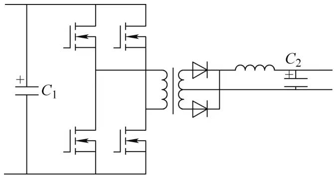
Figure 1-1 Bridge converter circuit
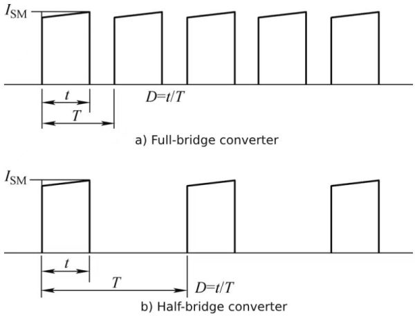
Figure 1-2 Input current of bridge converter
For the convenience of analysis, it is assumed that the input current waveform is a rectangular wave.
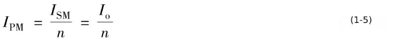
At this time, the relationship between the input current peak value and the output current is
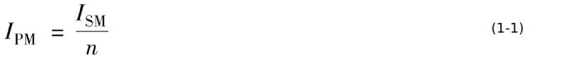
In the formula, IPM, ISM, and n are the primary side current peak value, secondary side current peak value, and transformer current ratio of the bridge converter, respectively.
The relationship between the input current average value Iav and the peak value is

The relationship between the input current effective value Irms and the peak value is

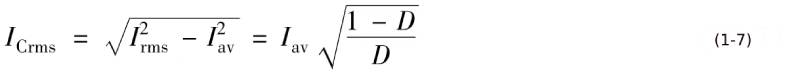
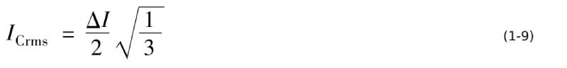
The effective current value ICrms of the DC-Link capacitor is

For the convenience of analysis, it is assumed that
but

Similarly, the relationship between the effective current value of the DC-Link capacitor (the AC current component of the DC bus current) and the average value of the DC bus current can be obtained as
The relationship between the ratio of the current effective value of the DC-Link capacitor/the average value of the output current and the duty cycle is shown in Table 1-1.
Table 1-1 Relationship between DC-Link capacitor current and duty cycle
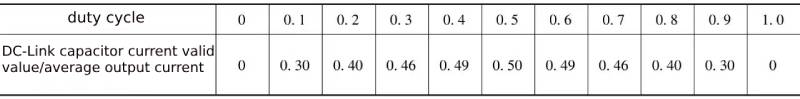
Converting the data in Table 1-1 into graphics can describe the relationship between the two more intuitively, as shown in Figure 1-3.
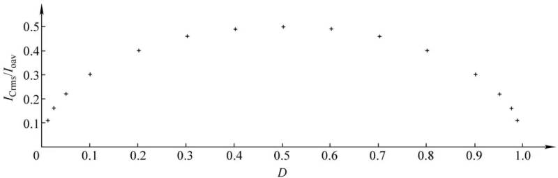
Figure 1-3 The relationship between the ratio of the effective current value of the DC bus capacitor and the average value of the output current and the duty cycle
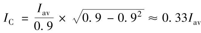
If the duty cycle is set to 0.9, the effective value of the output current of the DC bus is
n the same way, when the duty cycle is 0.8, IC is 0.5Iav, and when the duty cycle is 0.5, IC is Iav.
It can be seen that in the case of the average DC bus current, as the duty cycle decreases, the current in the DC bus capacitor increases.
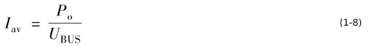
As the DC bus voltage increases, the average DC bus current decreases under the same output power, and the duty cycle decreases. The average DC bus current at this time is
When the duty cycle of the switching tube is 0.9, we can get from equation (1-8)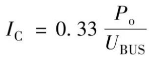
In the same way, the relationship between the duty cycle of different switching tubes and the current coefficient flowing through the DC bus capacitor can be obtained, as shown in Table 1-2.
Table 1-2 The relationship between different switching tube duty cycles and the current coefficient flowing through the DC bus capacitor

To sum up, the following conclusions can be drawn:
1 The working state of the DC bus capacitor of the symmetrical half-bridge converter is the same as that of the full-bridge converter except that the operating voltage is half of the DC bus voltage.
2 The DC bus capacitors of the non-isolated buck converter operate in the same manner as the DC bus capacitors of the full-bridge converter.
Working status of electrolytic capacitor – The above is the analysis of the working mode of the input capacitor of the bridge converter
2 Working status of electrolytic capacitors -Input capacitor operating modes of forward converter and asymmetric half-bridge converter
The forward converter is a type of isolated buck converter. Different from the full-bridge converter, in most cases, the duty cycle of the switching tube of the forward converter must not be greater than 0.5. Generally it is 0.35~0.4. The current waveform obtained by the corresponding forward converter from the DC bus is an approximate rectangular wave current waveform with a duty cycle less than 0.5.
When the duty cycle of the switching tube is 0.4, according to equation (1-8) we can get
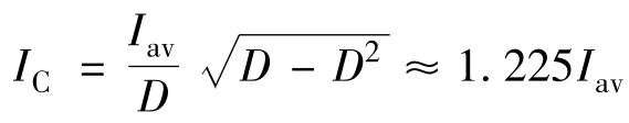 According to equation (1-9), the current of the capacitor is

In the same way, the relationship between the duty cycle of different switching tubes and the current coefficient flowing through the DC bus capacitor is shown in Table 1-3.
Table 1-3 The relationship between the duty cycle of different switching tubes and the current coefficient flowing through the DC bus capacitor

The DC link capacitors of the asymmetric half-bridge converter operate in the same manner as the DC link capacitors of the forward converter.
Working status of electrolytic capacitors -The above is an analysis of the input capacitor operating modes of forward converters and asymmetric half-bridge converters.
3 Working status of electrolytic capacitors -Operating modes of output rectifier and output filter capacitor
Bridge converters, forward converters, and asymmetric half-bridge converters all have an inductor in front of the output filter capacitor. Due to the inductor’s ability to suppress changes in current, the output current of the inductor becomes smooth. The main waveforms of the converter output current in the continuous state are shown in Figure 1-4.
In Figure 1-4, the current fluctuation part is the current of the output capacitor, and its DC component is sent to the load.
Therefore, the effective current value of the output filter capacitor is
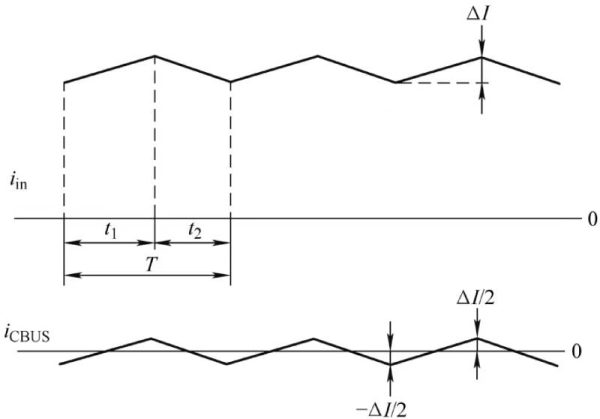
Figure 1-4 The main waveforms of the converter output current in the continuous state
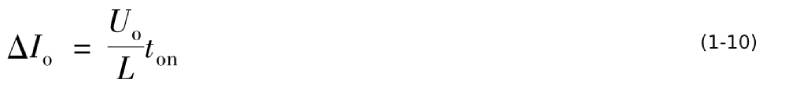
In the formula, ΔI is the fluctuation peak value of the converter output current in a switching cycle. This value is determined by the switching cycle ton, the inductance of the boost inductor, and the duty cycle. Therefore, ΔI is
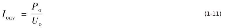
Or take 10% to 20% of the average value of the converter output current. The average value of the converter output current is
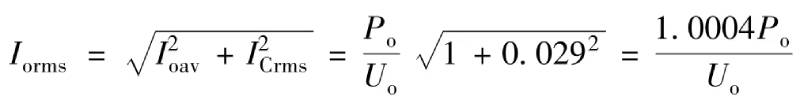
If ΔI is chosen to be 10% of the average value of the converter output current, then the effective current value of the output filter capacitor is
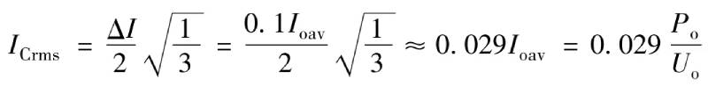
The effective value of the output current of the converter when the current is continuous is
If ΔI is chosen to be 20% of the average value of the converter output current, then the effective current value of the output filter capacitor is
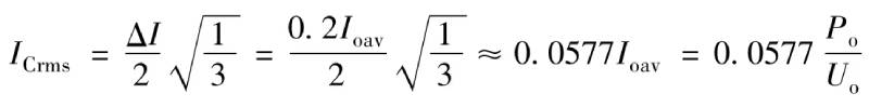
This current is only equivalent to less than 6% of the average output current of the converter, which is a very low current value for the output filter capacitor.
The effective value of the output current of the converter when the current is continuous is
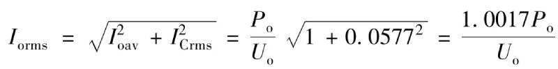
It can be seen that even if the current fluctuation is selected to be 20% of the converter output current, the effective value of the converter output current is only less than 0.2% higher than the average current value. It can be approximately considered that the average output current of the converter is equal to the output current. Valid values are equal.
Working status of electrolytic capacitors—the above is an analysis of the working modes of the output rectifier and output filter capacitors
Summarize:
Working status of electrolytic capacitors – This article mainly talks about the working modes of bridge converters, forward converters, asymmetric half-bridge converters, output rectifiers and output filter capacitorsIf you want to know more about electrolytic capacitors, please click:https://xuanxcapacitor.com