Choosing between an MLCC and a film capacitor comes down to one question: is this position about density and frequency, or about voltage, current and life? MLCCs win the first — decoupling, bypass and high-frequency filtering, where low ESR, low ESL and a tiny footprint are the whole point. Film capacitors win the second — DC-Link, snubber, AC filtering and EMI positions, where high voltage, high ripple current, stable capacitance and a long, self-healing life matter more than size. When MLCC supply tightens, a film part can take over some of those power positions. It cannot replace an MLCC in decoupling.
That distinction stopped being academic in 2026. MLCC lead times have stretched toward ten months on AI server demand, and buyers who once designed in an MLCC without a second thought are now being asked to look at alternatives. Film capacitors are the most common answer — but only where the electrical job allows it. This guide compares the two technologies on the parameters that actually decide the choice, then shows where a swap is realistic and where it is a reliability risk.
MLCC vs Film Capacitor at a Glance
| Parameter | MLCC | Film capacitor |
|---|---|---|
| Typical capacitance | pF to tens of µF | nF to hundreds of µF |
| Voltage range | Low to a few hundred volts | Hundreds to thousands of volts |
| ESR and ESL | Very low; excellent at high frequency | Low ESR, higher ESL than MLCC |
| Capacitance stability | Class 2 drops under DC bias, temperature and aging | Flat across voltage and temperature |
| Ripple current | Limited per part | High; built for DC-Link duty |
| Failure mode | Can fail short | Self-healing, usually fails open |
| Size per µF | Smallest | Larger |
Where MLCC Wins
The MLCC’s advantage is density and speed. A multilayer ceramic part puts a useful capacitance into a package a few millimetres across, with ESR and ESL low enough to work at hundreds of megahertz. That is why it dominates decoupling and bypass: an IC’s power pin needs a capacitor that can respond to a fast transient and sit right next to the pin, and no film part competes on that combination of size and frequency response.
Class 1 ceramics such as C0G (NP0) add a second strength: a capacitance that barely moves with temperature, voltage or time. For timing circuits, oscillators and RF matching, that stability is worth more than capacitance density, and it is the reason C0G parts hold their place even where a film capacitor would be electrically acceptable.
The limits appear as soon as the job changes. Class 2 dielectrics such as X7R and X5R give far more capacitance per volume, but they lose it under DC bias — a part rated 10 µF can measure well under that at half its rated voltage — and they age and drift with temperature. Where the design needs a defined capacitance at the working voltage, the MLCC’s headline number can be misleading.
Where Film Wins
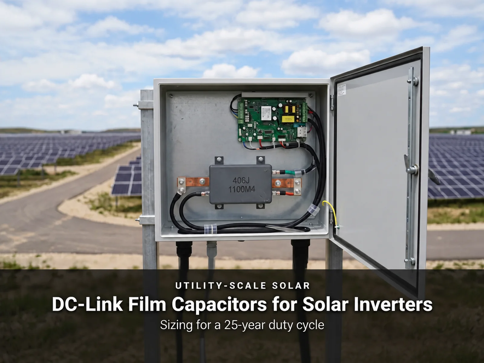
Film capacitors are built for power. A metallized polypropylene or polyester part handles high voltage, high ripple current and continuous AC stress without the capacitance collapse that afflicts Class 2 ceramics. Its capacitance is stable across voltage and temperature, so the value on the datasheet is the value in the circuit. For a DC-Link in an 800 V SiC inverter, that predictability is not a luxury; it is the basis of the ripple and lifetime calculation.
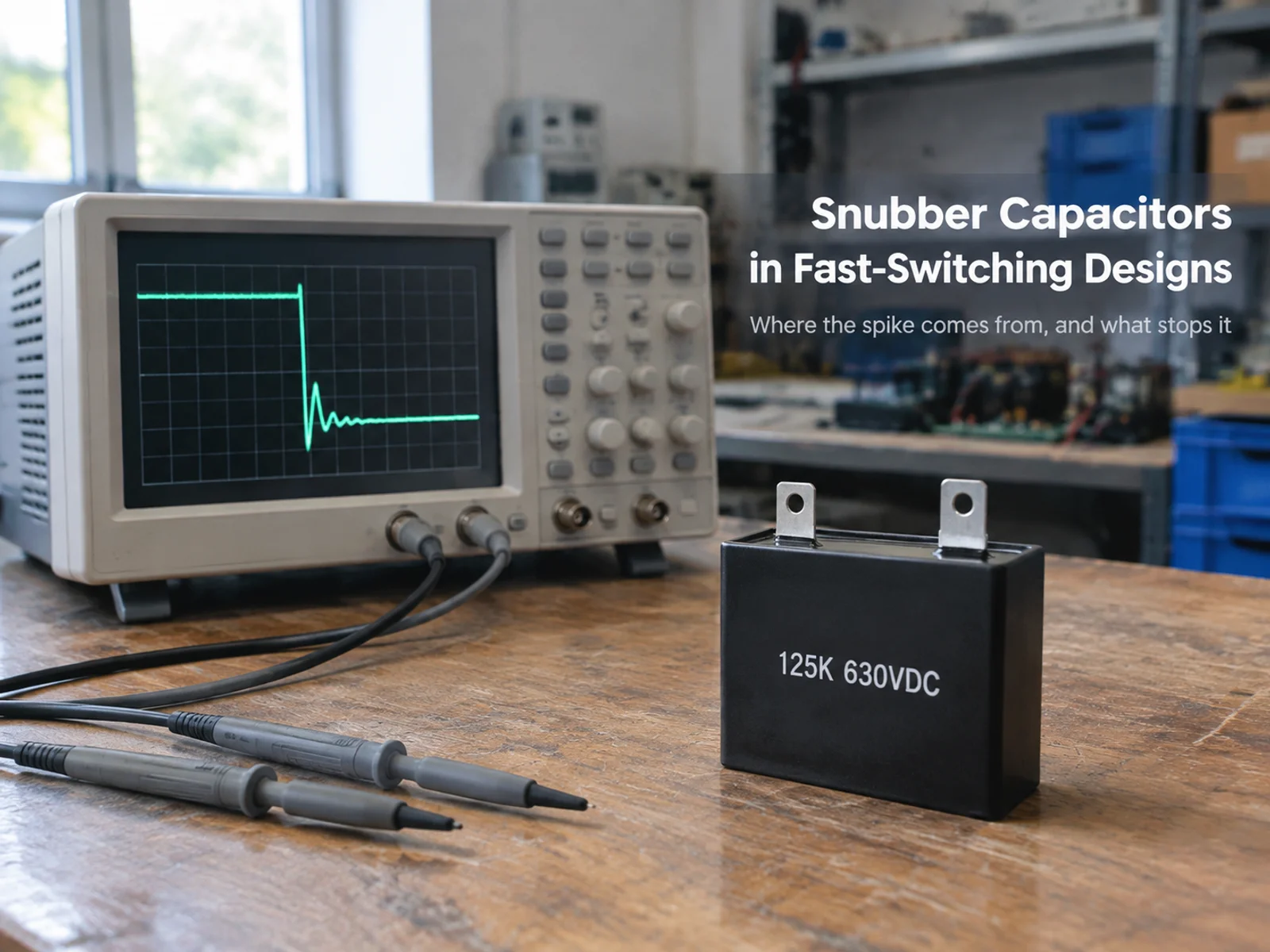
The second advantage is how it fails. Metallized film is self-healing: a local breakdown vaporizes a tiny area of the metallization and clears the fault, so the capacitor usually loses a little capacitance and keeps working rather than shorting. That behaviour is why film parts are preferred in snubber, safety and DC-Link positions, where a short-circuit failure can take out a switching device or trip a protection circuit.
The trade-off is size and cost at low voltage. A film part that matches an MLCC’s capacitance in a 5 V decoupling position would be many times larger and more expensive, which is why the substitution only makes sense where the electrical duty justifies it. If you are comparing film families, our guide to film capacitor types and how they work covers the metallized and foil constructions and what each is for.

Can Film Actually Replace MLCC?
Sometimes yes, sometimes no, and the line is drawn by the circuit’s job rather than by the capacitor’s specifications.
Positions where film is a real substitute
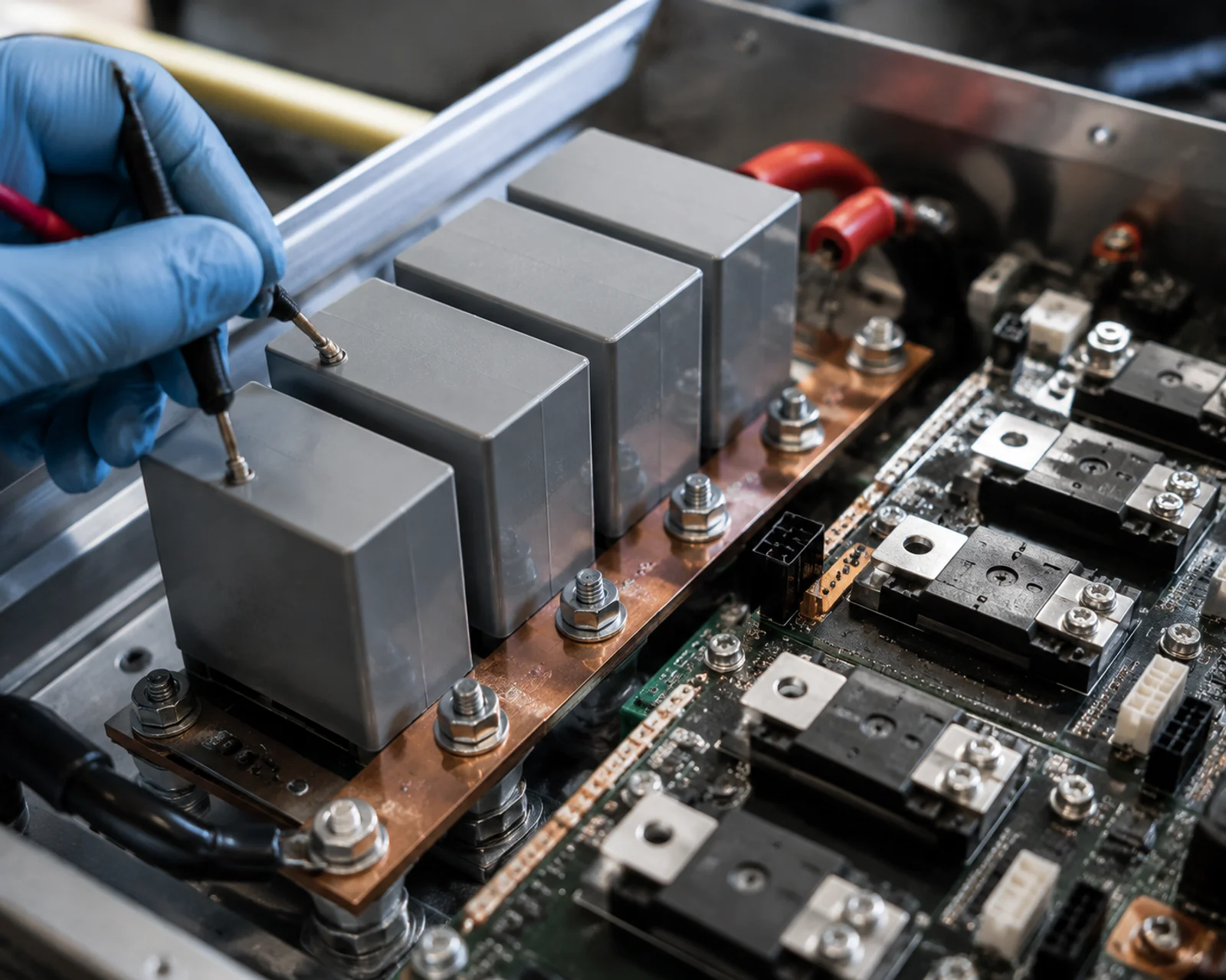
Bulk and DC-Link capacitance is the clearest case. Here the requirement is energy storage and ripple handling at a defined voltage, and a film part often does it better than a bank of Class 2 MLCCs, because it does not lose capacitance under bias and it tolerates far more ripple current. Snubber circuits are a second natural fit, where the self-healing failure mode and high dV/dt capability matter. AC line filtering and EMI positions — the X and Y capacitors in a power supply — are already film or safety-ceramic territory, and substituting a film part there is standard practice rather than a workaround.
Positions where it is not
Decoupling a fast digital or RF IC is not one of them. The MLCC’s low ESL and small package are what let it sit beside the pin and respond before the voltage collapses; a film part with a longer internal path and larger body cannot take that role, and trying to force it produces a design that is larger and still worse. High-density filtering at low voltage has the same problem, and so do timing and RF circuits that depend on a stable, small-value part in a small footprint. In these positions the right response to an MLCC shortage is to qualify a second MLCC source, not to redesign around a film capacitor.
How the 2026 Supply Picture Changes the Decision
Supply risk is now part of the selection. With MLCC lead times approaching ten months, a design that depends entirely on one ceramic part family carries a schedule risk that no amount of engineering elegance fixes. The practical response is a dual-design strategy: keep the MLCC where its electrical role is irreplaceable, but move the positions where a film part is genuinely equivalent onto film, so that a shortage in one family does not stop the whole board.
That is a sourcing decision as much as a technical one. The demand behind the current shortage is the same AI server power demand that has stretched the whole passive components chain, and it is unlikely to reverse quickly. Buyers who map which positions can accept a film alternative before the shortage reaches them are the ones who keep their production lines running.
A Selection Checklist
Start from the electrical job. Is this position storing energy, filtering ripple, snubbing a switch, or decoupling a fast pin? Only the first three are film candidates.
Check the voltage. Film wins comfortably above a few hundred volts; below that, the size penalty grows and the MLCC usually stays.
Compare at the working voltage, not the rated voltage. An MLCC’s Class 2 capacitance is measured at a fraction of its rating, so compare the film value against the MLCC’s derated value, not its headline number.
Check the failure mode. Where a short is dangerous, film’s self-healing behaviour is a safety argument as well as a technical one.
Check the footprint and the board. A film part that does not fit is not a substitute. Measure before you commit.
Qualify before you need it. The value of a film alternative comes from having it qualified when the MLCC goes short, not from discovering it during a shortage.
FAQ
Is a film capacitor a drop-in replacement for an MLCC?
No. The capacitance may match, but the ESR, ESL, size and self-healing behaviour are different, so a film part is a substitute only where the circuit’s requirements allow it — typically bulk, DC-Link, snubber and AC filtering, not decoupling.
Why does an MLCC lose capacitance under DC bias but a film capacitor does not?
The ferroelectric ceramic in Class 2 dielectrics such as X7R changes its dielectric constant as the applied field rises, so the measured capacitance falls with voltage. Film dielectrics are not ferroelectric in the same way, so their capacitance stays essentially flat across the working voltage.
Are film capacitors more expensive than MLCCs?
At low voltage and small capacitance, yes — often several times more per µF. At high voltage and high ripple current the comparison reverses, because a film part can replace a large bank of ceramics and tolerates the ripple the ceramics cannot.
Which is better for high-temperature operation?
It depends on the dielectric and the construction rather than the technology label. Class 1 ceramics hold capacitance across a wide temperature range, while Class 2 parts drift. Film parts are stable with temperature but have their own upper limit, typically 85 °C to 125 °C depending on the film and construction. Always check the specific datasheet.
Choosing between the two is easier when you compare them on the parameter that decides the position, not on a single headline number. If you are weighing a film alternative against an MLCC that has gone short or expensive, send us the circuit conditions, the working voltage and the capacitance you need, and we will confirm whether a film capacitor is a genuine substitute or whether the multilayer ceramic capacitor should stay in the design. We will quote against the real specification and lead time you need.