
Selecting the right film capacitor for an 800V SiC inverter comes down to four core criteria: voltage rating with 1.3–1.5× derating (an 800V bus demands 1000–1200V DC-rated parts), low ESL (under 20–50 nH to match SiC’s fast dv/dt edges), ripple-current rating that covers the switching-frequency spectrum, and a temperature class that survives the operating environment—125 °C for automotive, 105 °C for industrial. DC-link applications call for high capacitance (tens to hundreds of microfarads), snubbers need small, low-ESL devices (0.1–1 µF), and output filters sit in between (a few microfarads). Miss any one of these specs and you risk over-voltage spikes, excessive heat, or premature failure.
Why 800V SiC Inverters Demand Specific Film Capacitor Specs
Silicon-carbide switches turn on and off in nanoseconds, generating dv/dt slopes measured in tens of kilovolts per microsecond. Any stray inductance in the DC bus converts that di/dt into a voltage spike—L · di/dt—which adds directly to the 800V rail. Electrolytic capacitors, with ESL often exceeding 50 nH, amplify those spikes beyond the semiconductor’s safe operating area. Film capacitors offer ESL as low as 10–20 nH in well-designed packages, keeping transient over-voltage manageable.
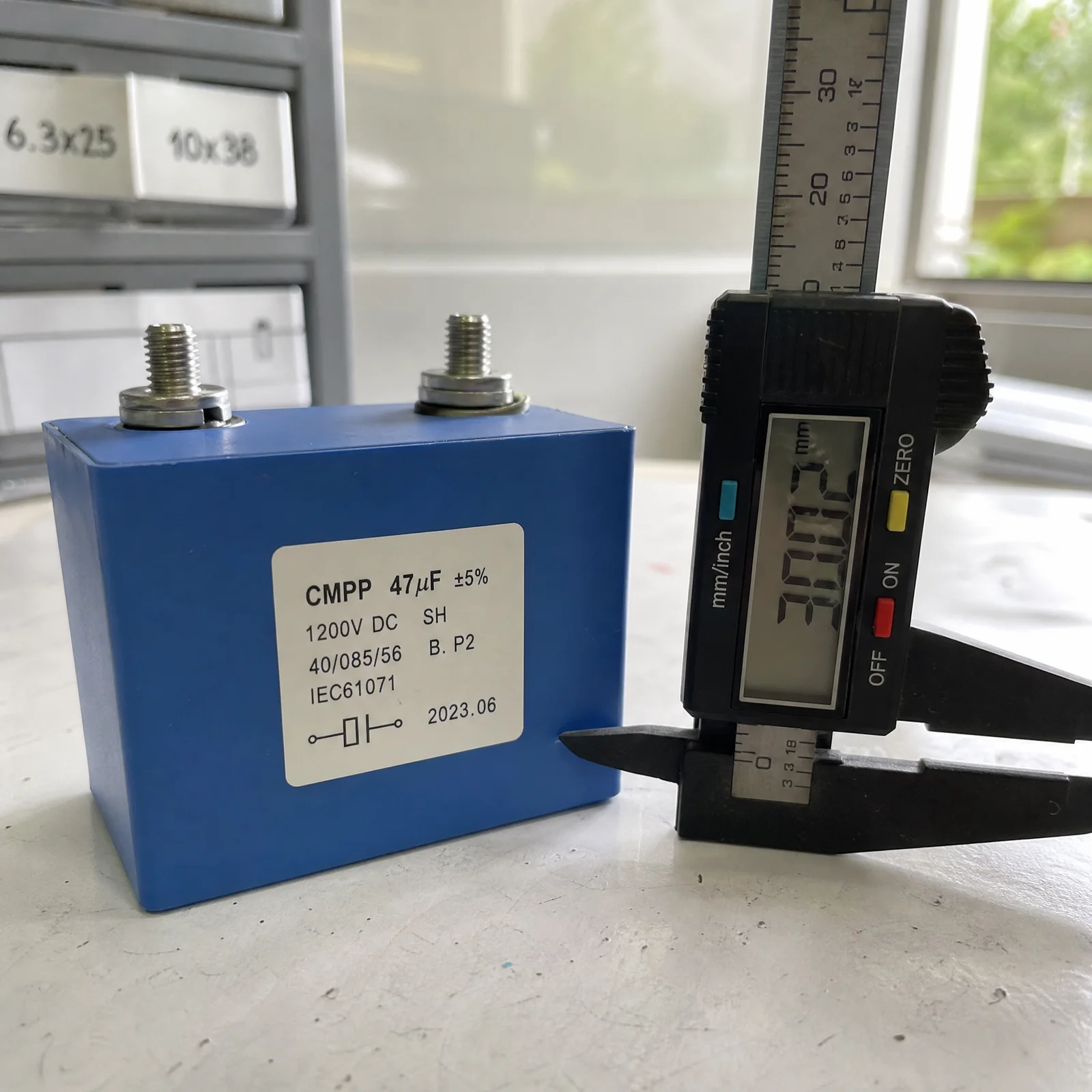
The 800V bus itself sits near the upper edge of many legacy capacitor families. Film dielectrics—polypropylene in particular—scale cleanly to 1000V, 1200V, and beyond, with voltage derating rules that preserve decades of service life. High switching frequencies, common in SiC designs (50–200 kHz), spread ripple current across a wide spectrum; film’s low dissipation factor keeps self-heating in check where electrolytics would overheat.
Step 1: Voltage Rating and Derating
Start with the DC-bus nominal voltage—800V in this case—and multiply by 1.3 to 1.5. That yields a required capacitor rating of 1040–1200V DC. The extra margin accounts for manufacturing tolerance, transient over-voltage during regenerative braking or fault conditions, and temperature-dependent dielectric strength. Running a 1000V-rated capacitor at 800V leaves 20 % headroom; a 1200V part offers 50 %, which extends life in harsh environments.
Industry practice leans toward 30–40 % derating for mission-critical applications (automotive traction, grid-tie inverters) and 20–30 % for cost-sensitive industrial drives. If peak transients can reach 900V for milliseconds, a 1200V rating becomes the safer choice. Consult the manufacturer’s voltage-life curves: a part run at 70 % of rated voltage may last ten times longer than one stressed at 90 %.
Step 2: ESL and ESR for High dv/dt
Equivalent series inductance determines how much voltage spike appears during a fast switching edge. The formula Vspike = L · di/dt shows that even 30 nH of ESL, combined with a 1000 A/µs current slew rate, produces a 30V transient. SiC MOSFETs routinely hit 2000–5000 A/µs in hard-switched topologies, so ESL must stay below 20–50 nH. Film capacitors achieve this through stacked-foil construction, short internal leads, and surface-mount or low-profile packages.
Equivalent series resistance governs ripple-current heating. A 20 mΩ ESR dissipating 10 Arms ripple generates 2 W of heat—manageable with good thermal coupling to a heat sink or copper plane. Film ESR remains nearly flat across frequency, unlike electrolytics where ESR rises at high frequency. Parallel connections reduce both ESL and ESR: two identical capacitors in parallel halve the net inductance and quarter the resistance.
Step 3: Ripple Current Rating
Ripple current in an 800V SiC inverter has two origins: switching ripple from the DC-DC converter or active front end, and load-dependent harmonics from the three-phase inverter bridge. The total RMS ripple current is the root-sum-square of all frequency components.
DC-link capacitance sets the voltage ripple: C = I · Δt / ΔV, where I is the peak ripple current magnitude, Δt is half the switching period, and ΔV is the acceptable voltage deviation. For an 800V bus with ±1 % ripple tolerance (ΔV = 8V) and 100 kHz switching (Δt = 5 µs), a 20A peak current demands C = (20 A × 5 µs) / 8V ≈ 12.5 µF. Real designs add margin and account for capacitor aging, so 20–30 µF is common. High-power traction inverters (100+ kW) may use 100–200 µF or more.
Manufacturers specify ripple-current rating at a reference frequency (often 10 kHz or 100 kHz) and ambient temperature. Datasheet curves show how the rating changes with frequency and temperature. Film capacitors usually maintain or slightly improve their rating as frequency rises. Always verify that your calculated ripple current, adjusted for all harmonics, stays below the derated limit.
Step 4: Temperature Rating and Lifetime
Automotive traction inverters operate from −40 °C to +125 °C; industrial VFDs span −25 °C to +105 °C. Film capacitors are available in matching temperature classes: 85 °C, 105 °C, and 125 °C. The temperature rating refers to the maximum case or core temperature, not ambient. Self-heating from ripple current adds 5–20 °C depending on package size and thermal coupling.
Lifetime follows an Arrhenius relationship: every 10 °C reduction in core temperature roughly doubles service life. A capacitor stressed at 90 % of rated voltage and temperature might last 10 000 hours; derate to 70 % and life extends to 100 000 hours or more. Film dielectrics do not dry out like electrolytic electrolyte, so end-of-life is typically defined by gradual capacitance loss (5–10 %) or an increase in ESR.
Xuansn offers 800V to 1200V-rated polypropylene film capacitors in compact SMD and radial-lead formats, designed for low ESL and high ripple-current capability in SiC inverter DC-link stages. Typical ESL is under 30 nH, and 125 °C temperature class ensures automotive-grade reliability.
Common Questions About Selecting Film Capacitors for SiC Inverters
What DC-link capacitance value should I use?
Calculate C = I · Δt / ΔV using the peak ripple current, half the switching period, and your acceptable voltage ripple. For an 800V bus with ±1 % ripple and 100 kHz switching, expect 10–30 µF per kilowatt of inverter power. High-power systems may need 100–200 µF total, often split across multiple capacitors in parallel.
Can I substitute electrolytic capacitors for film capacitors?
Electrolytic capacitors offer higher capacitance density and lower cost, but their ESL (50–200 nH) and ESR cannot match film performance. At 800V and SiC switching speeds, the resulting voltage spikes and self-heating typically force you back to film. Electrolytic bulk capacitance is sometimes placed in parallel with film snubbers—the electrolytic handles low-frequency energy storage, the film suppresses high-frequency transients.
How do I verify my selection is adequate?
Prototype testing is essential. Measure DC-bus voltage ripple with a high-bandwidth oscilloscope and current probe on the capacitor terminals. Confirm that peak-to-peak ripple stays within ΔV, that no over-voltage spikes exceed the semiconductor rating, and that capacitor case temperature remains 10–20 °C below the rated maximum.
Choosing film capacitors for an 800V SiC inverter requires matching voltage rating (1.3–1.5× derating), ESL (under 20–50 nH), ripple current (calculated from switching and load harmonics), and temperature class (125 °C automotive, 105 °C industrial) to your application’s electrical and thermal environment. Our earlier article on 800V SiC DC-link requirements explains why these parameters matter; this guide shows you how to select them in practice. Xuansn manufactures high-voltage polypropylene film capacitors optimized for SiC inverter DC-link, snubber, and filter stages—low ESL, high ripple current, and automotive-grade temperature ratings. Contact our team at coco@xuanxcapacitors.com with your bus voltage, switching frequency, ripple current, and temperature range, and we will recommend a part number with verified performance data. Quote turnaround in 24 hours.