An 800 V SiC inverter pushes its DC-link film capacitor harder than any IGBT-based design did. The bus voltage climbs to the 800 V class, and the switching frequency rises from a few kilohertz to tens of kilohertz. Together these two shifts raise the ripple current the capacitor must carry, steepen the dv/dt across it, and concentrate more heat in a smaller part – which is exactly where a film capacitor either earns its place or becomes the weakest link.
This is the first article in our 800 V SiC series, following our work on eVTOL DC-link film capacitors. The question is specific: when the inverter goes SiC at 800 V, what changes for the DC-link capacitor – and what should you specify for it.
What Actually Changes When the Inverter Goes SiC
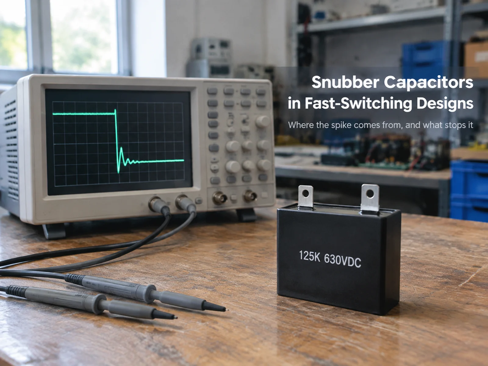
Silicon carbide switches do two things differently than silicon IGBTs. They switch faster, so the switching frequency moves from the single-digit kilohertz range up to tens of kilohertz. And they produce steeper voltage edges, because the transition from on to off happens in a fraction of the time.
Both changes land on the DC-link capacitor. A higher switching frequency shifts the ripple current the capacitor sees to higher frequencies and adds more harmonics. A steeper dv/dt means the capacitor has to absorb and release charge faster at the bus. The result is the same: more ripple current to carry, more self-heating, and a tighter temperature budget.
This is why the 800 V platform is not just a higher-voltage version of a 400 V design – the capacitor spec moves on two axes at once.
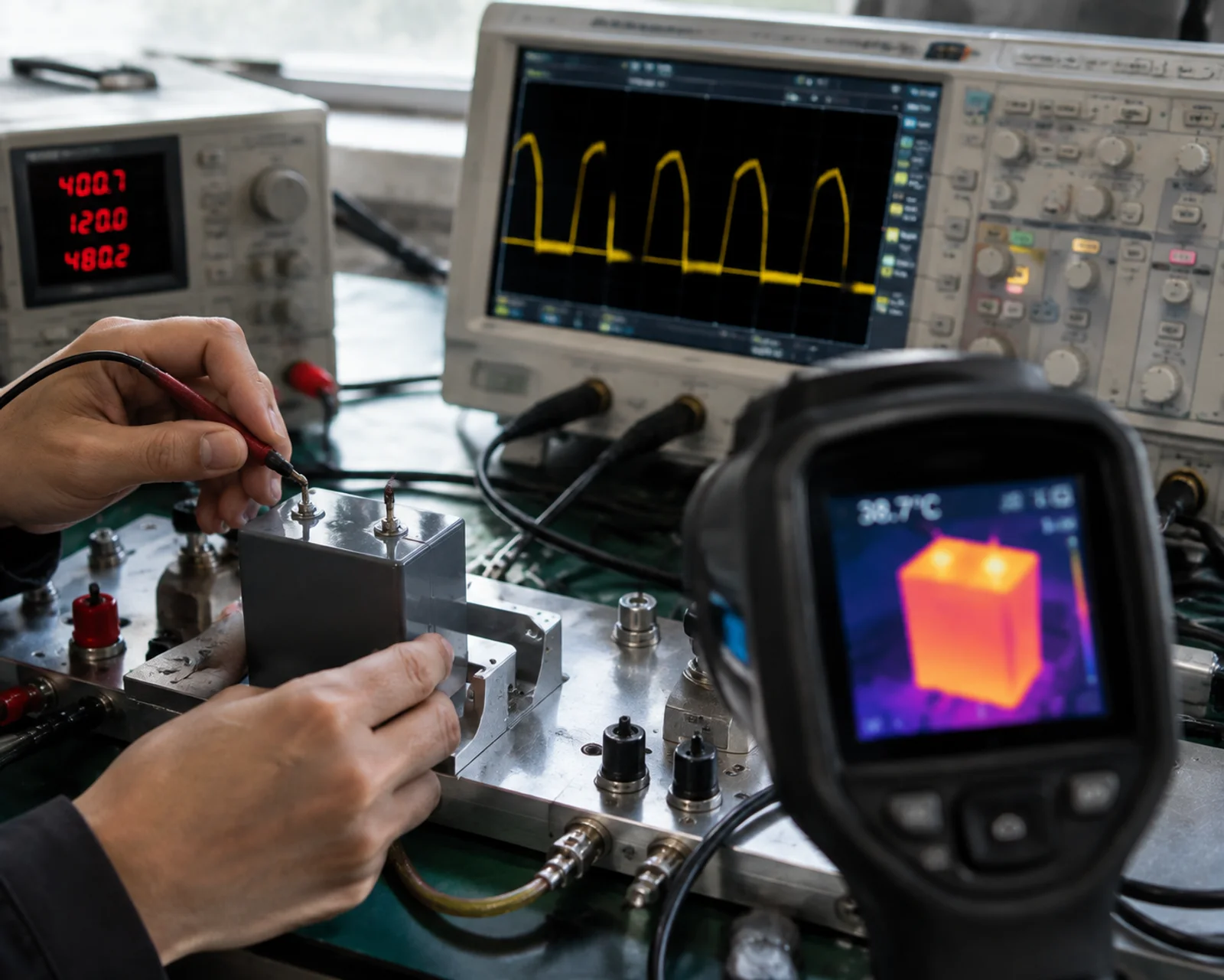
The Three Numbers an 800 V SiC Inverter Demands
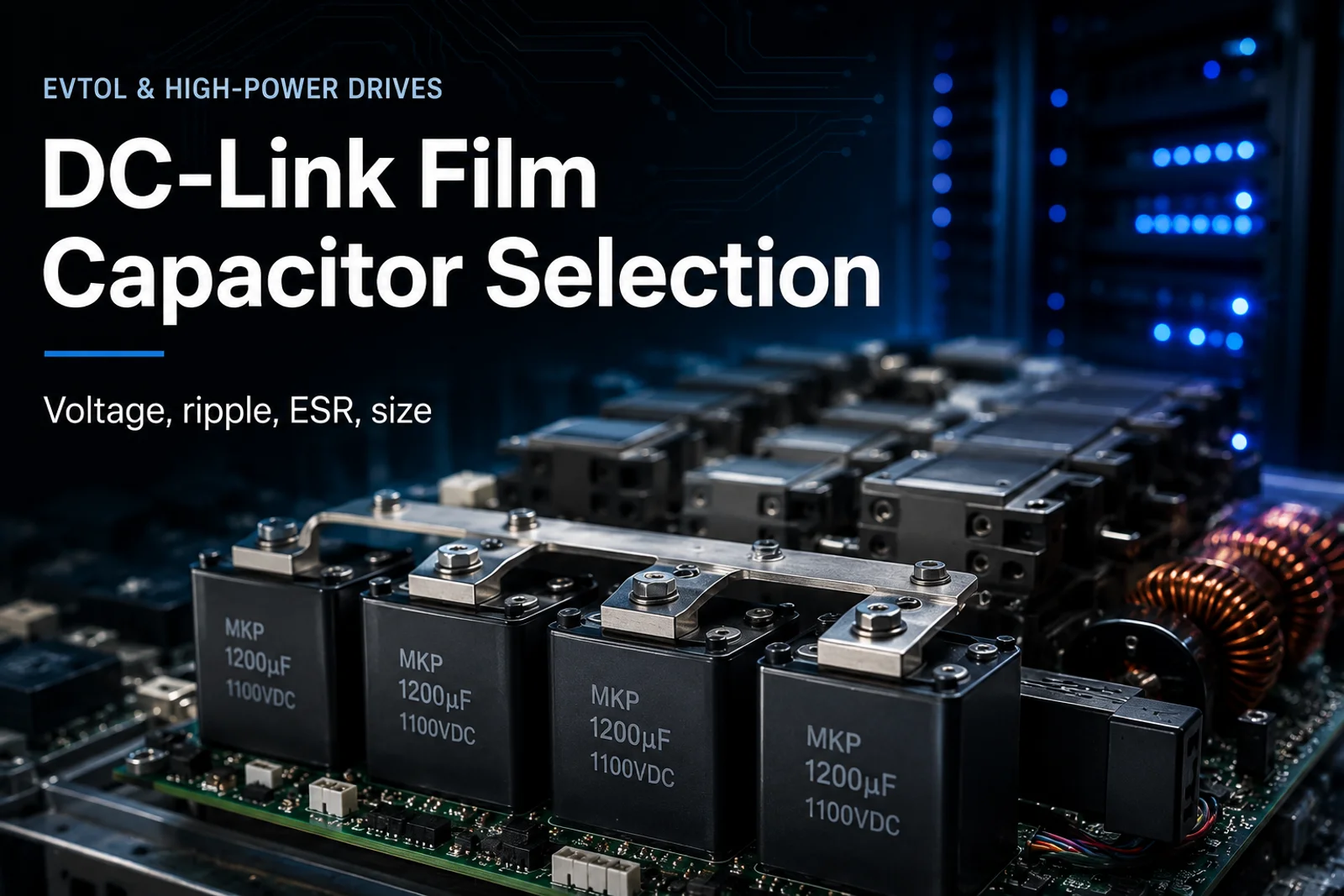
When you specify a DC-link film capacitor for an 800 V SiC inverter, three numbers carry most of the decision.
Ripple current at the switching frequency
Ripple current is the alternating current the capacitor handles on top of the DC bus. With SiC running at tens of kilohertz, the ripple sits higher in frequency and carries more harmonics, so the RMS current the capacitor sees goes up for the same power level. The rating that matters is the ripple current capability at your actual switching frequency – not at a reference frequency from the datasheet.
ESR and the heat it makes
Equivalent series resistance converts part of that ripple current into heat inside the capacitor. A lower ESR means less self-heating for the same ripple – and in a compact 800 V inverter, space for cooling is limited, so ESR quickly becomes the number that decides whether the capacitor survives. Film capacitors hold a low, stable ESR across temperature, which is one reason they suit this position well.
Voltage rating and dv/dt tolerance
The bus runs near 800 V, so the capacitor must be rated well above that with margin for overshoot during switching transients. And with SiC’s steep edges, the capacitor also needs enough dv/dt tolerance to absorb those transitions without generating excessive internal stress. Voltage rating and transient capability go together.
| Parameter | IGBT design (typical) | 800 V SiC design | Why it matters |
|---|---|---|---|
| Switching frequency | Few kHz | Tens of kHz | Higher ripple frequency, more harmonics |
| Ripple current | Moderate | Higher at the same power | More self-heating |
| dv/dt | Steeper | Steeper still | Capacitor absorbs faster edges |
| ESR requirement | Low | Lower | Heat budget is tight |
The pattern is clear: each move from IGBT to SiC tightens the capacitor’s requirement on ripple, ESR and voltage capability at once.
Why Film Beats Electrolytic in This Position
At the DC-link position of an 800 V SiC inverter, film has a structural advantage. A film capacitor carries a low, temperature-stable ESR and handles high ripple current, while its self-healing property means a localised failure clears itself rather than shorting the bus. An electrolytic capacitor in the same position drifts in ESR as it ages and heats – acceptable on a bulk rail, but harder to justify where the ripple current is high and the edge is steep.
This is the same argument our take on why eVTOL power electronics need DC-link film capacitors makes for electric aviation; here it applies to SiC drives.
Specifying for the 800 V Platform
When you are choosing a part, work down the list in order: ripple current capability at the switching frequency first, then ESR against your heat budget, then voltage rating with derating for overshoot, and finally the dv/dt tolerance and the form factor that fits the inverter. Checking them in that order catches the most common 800 V failures before the design is locked.
Xuansn manufactures film capacitors built for high-ripple, high-voltage power stages like this. Our film capacitor range covers the ratings an 800 V SiC DC link needs, and the film capacitor guide walks through the full selection logic.
Common Questions
What switching frequency does an 800 V SiC inverter typically run?
SiC inverters commonly switch in the tens of kilohertz – substantially higher than the few kilohertz typical of IGBT designs. Check the datasheet for your exact number, because the ripple current rating that matters is the one at your real switching frequency.
Do I need a film capacitor or can an electrolytic work at 800 V?
At the DC-link position with high ripple and steep edges, film is usually the better choice for its low ESR and self-healing. An electrolytic can suit a bulk rail where ripple is lower, but the DC link of an 800 V SiC inverter leans film.
What voltage rating should an 800 V DC-link capacitor have?
Rate well above the bus with margin for overshoot during switching. The exact figure depends on your overshoot envelope – confirm against the real transient, not just the nominal bus voltage.
Get a quote from Xuansn
Email: coco@xuanxcapacitors.com