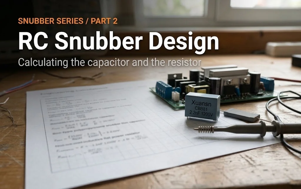
Film capacitors are among the most widely used passive components in power electronics, motor drives and EMC work. They are non-polarized, self-healing and highly reliable, which is why engineers reach for them when an electrolytic capacitor will not do. This guide covers how they are built, the main types, the parameters that matter, where they are used, and how to pick one.
What Is a Film Capacitor?
A film capacitor uses a thin plastic film as its dielectric. Two layers of film are wound or stacked with electrodes between them to form a compact component that stores electrical energy.
Unlike electrolytic capacitors, film capacitors are non-polarized, meaning they can be connected to a circuit in either direction. This makes them suitable for AC circuits where the current direction changes constantly.
The plastic film dielectric is the defining feature. It gives film capacitors several advantages over other technologies:
- Self-healing – when a small dielectric breakdown occurs, the metal electrode vaporizes around the fault, restoring insulation
- Low ESR and low inductance – ideal for high-frequency and high-ripple applications
- Long service life – no liquid electrolyte to dry out
- High voltage and current handling – available up to thousands of volts
- Stable capacitance over temperature and time
These properties make film capacitors the first choice for power electronics, motor control, EMI suppression, and high-reliability industrial applications.
How Does a Film Capacitor Work?
A film capacitor stores energy in an electric field between two conductive electrodes separated by the plastic film dielectric. When voltage is applied, charges accumulate on the electrodes.
Constructively, two metal electrodes (typically vacuum-deposited aluminum or zinc) sit on either side of a plastic film, wound into a cylinder or stacked into a flat block, then sealed with resin. Because there is no liquid electrolyte, film capacitors do not dry out and their capacitance stays stable over decades of operation – a key reliability advantage over aluminum electrolytic capacitors.
Types of Film Capacitors
Film capacitors are classified primarily by the dielectric material. Each material has different electrical characteristics and applications.
1. Polypropylene Film Capacitors (PP)
The most widely used film dielectric for power applications. Very low dielectric loss, high insulation resistance, excellent high-frequency behavior and good self-healing. Typical ratings up to 400V, 630V, 1000V and higher. Common series: CBB21, CBB22, CBB60, CBB61, CBB81. Applications: motor run, power factor correction, DC-link, snubber, high-frequency circuits.
2. Polyester Film Capacitors (PET / Mylar)
The most economical film type, widely used in general-purpose and consumer electronics. Low cost and compact, but higher dielectric loss and poorer high-frequency performance than polypropylene. Applications: coupling, bypass, timing circuits.
3. Polyphenylene Sulfide (PPS)
High-temperature stability (up to ~150°C), stable capacitance over temperature. Used in automotive, timing, and precision applications.
4. Polystyrene (PS)
Very low dielectric absorption and loss, but limited to low-temperature/low-voltage use. Rare in modern products.
5. PTFE (Teflon)
Extremely low loss, very high temperature rating. Expensive, used in aerospace and high-reliability military applications.
By Construction
| Type | Structure | Characteristics |
|---|---|---|
| Metallized film | Thin metal layer deposited directly on film | Self-healing, smaller size, most common |
| Film / foil | Separate metal foil layers with film | Higher current handling, no self-healing, used for high-current pulse applications |
By Safety Classification
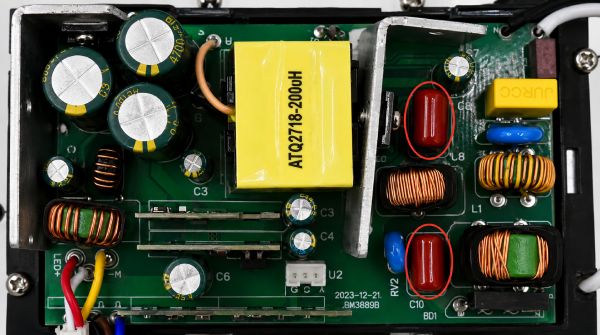
X capacitors connect across the line (line-to-line). X1, X2, X3 classes by impulse withstand. Y capacitors connect from line to ground. Y1, Y2, Y4 classes by isolation rating. Safety film capacitors are certified to EN 60384-14, UL 60384-14 and IEC 60384-14, and are mandatory in AC mains-powered equipment for EMI suppression.
Key Parameters & How to Read Them
- Rated Voltage (UR) – the maximum continuous DC voltage. Always derate: operate at 70-80% of rated voltage for long life.
- Capacitance (C) – measured in µF, nF, or pF, with tolerance typically ±5% (J), ±10% (K), or ±20% (M).
- Dissipation Factor (DF / tan δ) – a measure of dielectric loss. Lower is better. Polypropylene has very low DF, polyester is higher.
- dv/dt – the maximum rate of voltage change in V/µs. Critical for snubber and high-pulse applications.
- ESR – combined resistance of the capacitor. Lower means less energy lost as heat.
- Insulation Resistance (IR) – how well the dielectric resists leakage current. Higher is better.
- Operating Temperature Range – typically -40°C to +85°C (or +105°C for high-temperature grades).
- Self-Healing – the ability to recover from localized dielectric breakdown.
Film Capacitor Applications
DC-Link in Inverters and Converters
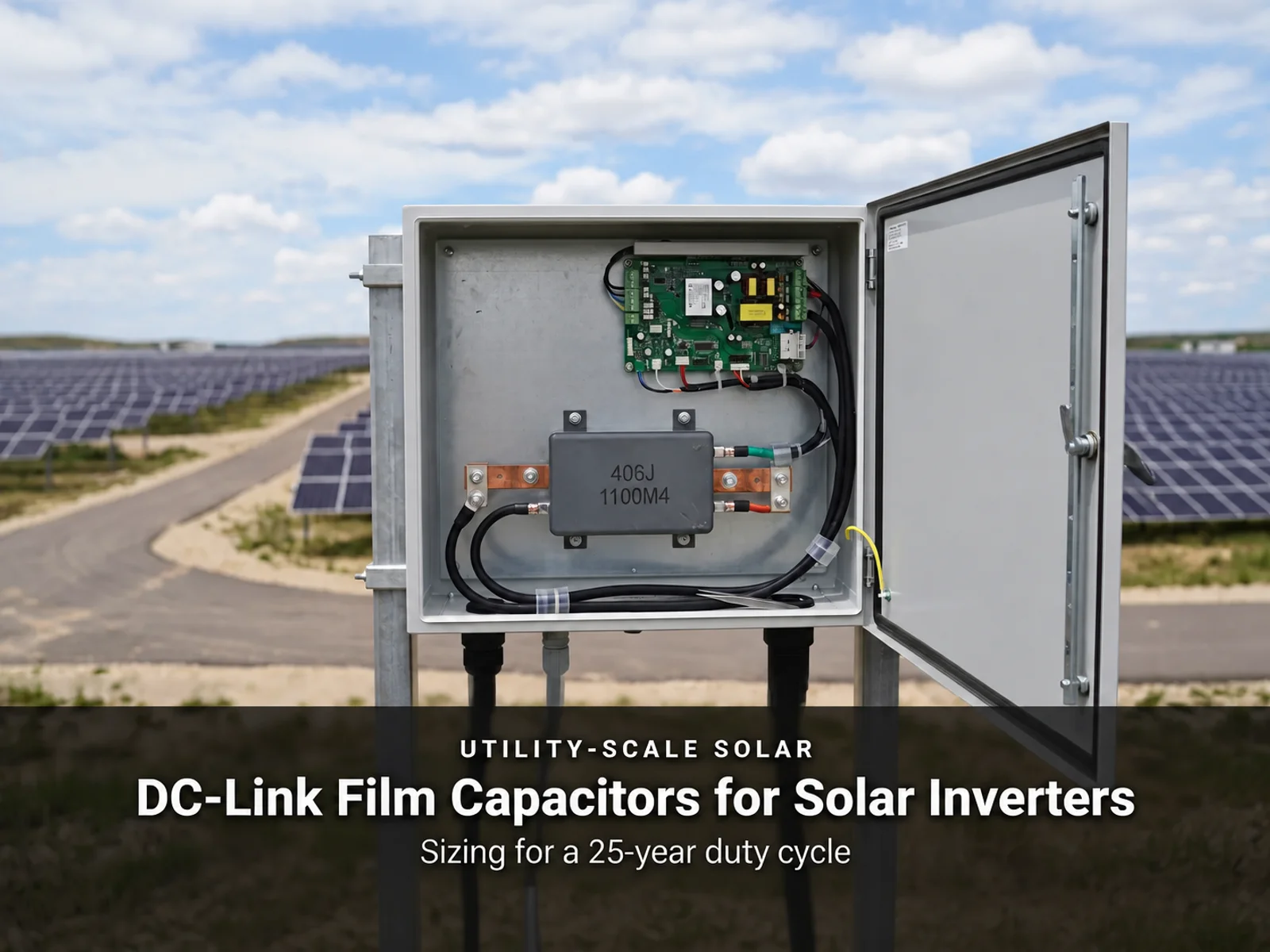
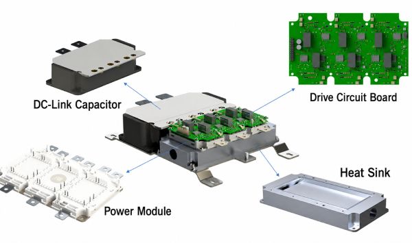
DC-link film capacitors smooth the DC bus voltage in frequency converters, EV inverters, solar inverters and wind converters. Low ESR and high ripple current capability make film the preferred choice over electrolytic in high-power systems. Related products: Film capacitor range.
Motor Run and Start Capacitors
Motor run capacitors provide phase shift in single-phase AC motors (fans, pumps, compressors, air conditioners). Motor start capacitors provide a high-torque starting pulse. Related products: CBB61 motor capacitor.
EMI Suppression (X2 / Y Capacitors)
Safety film capacitors suppress electromagnetic interference in AC mains-powered equipment – power supplies, appliances, industrial machines. They are required for EMC compliance. Related products: X2 / X safety capacitors and Y capacitors.
Snubber Circuits
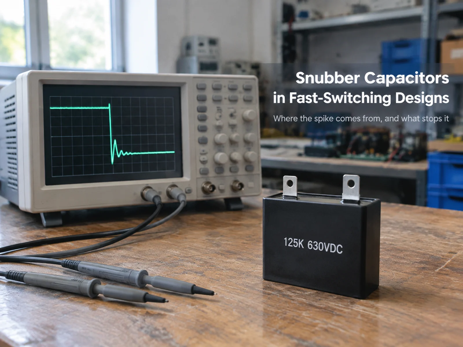
In IGBT/SCR power switches, snubber film capacitors limit dv/dt and suppress voltage spikes during switching transitions, protecting the semiconductor. Related products: Snubber capacitors.
High-Frequency / Resonant Circuits
Polypropylene film capacitors handle high-frequency AC currents in induction heating, resonant converters and RF filtering with low loss.
Power Factor Correction & Pulsed Power
In industrial power systems, film capacitors compensate reactive power and improve power factor. High-voltage film/foil capacitors also deliver controlled high-energy pulses in medical equipment, lasers and research.
Film vs Electrolytic vs Ceramic: Which to Choose?
| Criterion | Film Capacitor | Electrolytic | Ceramic (MLCC) |
|---|---|---|---|
| Polarity | Non-polarized | Polarized | Non-polarized |
| Capacitance density | Medium | Very high | Low-medium |
| Voltage rating | High | Medium-high | Medium |
| ESR / loss | Very low | High | Medium |
| High-frequency | Excellent | Poor | Good |
| Lifespan | Very long | Limited (dries out) | Long |
| Self-healing | Yes (metallized) | No | No |
Rule of thumb: need high capacitance in small space, DC only → electrolytic. Need high-frequency/low-loss/high-voltage/long-life → film. Need small-value decoupling → ceramic.
Film Capacitor Selection Guide (Step by Step)
- Define the circuit function – DC-link, motor run, EMI suppression, snubber, coupling, or resonant?
- Determine rated voltage – operating voltage × 1.25-1.5 derating factor. For AC, use the AC voltage rating.
- Calculate capacitance – based on ripple current, energy storage, or impedance requirement.
- Check dv/dt – for switching circuits, verify the dv/dt rating exceeds the actual switching speed.
- Verify ripple current / ESR – ensure the capacitor can handle the RMS ripple without overheating.
- Select the dielectric – polypropylene for power/high-frequency, polyester for general purpose.
- Check safety certification – for AC mains use, select X2/Y capacitors with EN/IEC/UL certification.
- Confirm temperature range – cover ambient temperature with margin.
- Choose packaging – radial lead, axial, SMD, or screw terminal based on mounting.
Film Capacitor Lifetime and Reliability
Film capacitors are among the most reliable capacitor technologies. Key factors affecting lifetime: voltage stress (derating extends life), temperature (every 10°C rise roughly halves lifetime), ripple current (excessive ripple heats internally), and moisture (keep in dry storage). Under normal operating conditions, quality film capacitors can last 20+ years.
Common Film Capacitor Failure Modes
- Open circuit – often caused by electrode corrosion or mechanical stress
- Capacitance loss – gradual degradation of the dielectric
- Short circuit – rare with metallized film due to self-healing; more common with film/foil
- Humidity ingress – moisture penetration through imperfect sealing
How to Test a Film Capacitor
- Visual inspection – check for bulging, cracking, or resin damage
- Capacitance measurement – use an LCR meter at the rated frequency
- Insulation resistance – measure IR; a low value indicates dielectric degradation
- DF / ESR test – high dissipation factor indicates aging
- Withstand voltage test – for critical applications, verify with a hipot tester at reduced voltage
How to Read Film Capacitor Markings
Most film capacitors carry a code printed on the body, for example CBB21 104K 250V. Here is how to decode it:
- CBB21 – series designation (CBB = metallized polypropylene film)
- 104 – capacitance in pico-farads: 10 followed by 4 zeros = 100,000 pF = 100 nF = 0.1 µF
- K – tolerance, ±10%
- 250V – rated DC voltage
The capacitance code works the same for all film types: the first two digits are significant figures, the third digit is the number of zeros, and the unit is always pF. 473 means 47,000 pF = 47 nF; 222 means 2,200 pF = 2.2 nF.
Common Film Capacitor Series and Their Uses
Different series are designed for different jobs. This table shows the most common film capacitor series and where to use them:
| Series | Dielectric | Typical Use |
|---|---|---|
| CBB21 | Polypropylene | General pulse circuits |
| CBB22 | Polypropylene | Switching power supplies |
| CBB60 | Polypropylene | Motor run, AC circuits |
| CBB61 | Polypropylene | Fan motor, small motors |
| CBB81 | Polypropylene | High dv/dt snubber |
| CL11 | Polyester | General purpose |
| CL21 | Polyester | Coupling and bypass |
| X2 | Polypropylene | EMI suppression (AC mains) |
Two Real-World Selection Examples
Example 1: DC-link capacitor in a 10 kW solar inverter. A 10 kW three-phase solar inverter has a DC bus at 400-800 V with heavy ripple from the switching stage. Choose a polypropylene film capacitor rated 450 VDC (two in series derate the 800 V bus), with low ESR to handle the ripple current. A 40 µF / 450 V metallized polypropylene DC-link capacitor with screw terminals is typical for this class.
Example 2: Motor run capacitor in a 1 HP air conditioning compressor. A single-phase compressor motor needs a run capacitor to shift the phase of the auxiliary winding. Choose a CBB60 or CBB61 polypropylene capacitor rated at 450 VAC, with capacitance between 20-50 µF depending on the motor specification. Because the capacitor operates continuously, long-life construction and a sealed casing are essential.
FAQ
Q: What is the difference between a film capacitor and an electrolytic capacitor?
A: Film capacitors are non-polarized, have much lower loss, longer life, and better high-frequency performance, but lower capacitance density. Electrolytics offer high capacitance in a small package but are polarized and have limited life.
Q: Are film capacitors polarized?
A: No. Film capacitors are non-polarized and can be connected in either direction.
Q: What does “self-healing” mean?
A: When a local dielectric breakdown occurs in a metallized film capacitor, the thin metal electrode around the fault vaporizes, isolating the defect and allowing the capacitor to continue working.
Q: How long do film capacitors last?
A: With proper derating, 20+ years. Temperature and voltage stress are the main factors.
Q: Can I replace an electrolytic capacitor with a film capacitor?
A: Only when the circuit can accept a physically larger, non-polarized part with a lower capacitance value. On DC-link and power supply circuits, a film capacitor can often take the place of an electrolytic one.
Q: What is an X2 capacitor?
A: An X2 safety capacitor is built to suppress electromagnetic interference across the AC line, and is certified to EN/IEC 60384-14.
Need Help Choosing a Film Capacitor?
Xuansn is a film capacitor manufacturer. Our range covers CBB series, X2 safety capacitors, DC-link capacitors and motor run capacitors. Our engineers can supply samples and custom specifications matched to your application.
Send us your circuit parameters – voltage, capacitance, frequency and mounting – and we will come back with a recommendation within 24 hours.