1.Overview
🐾Mica is an extremely important and excellent inorganic insulating material. As a dielectric material, it has not yet been found that the comprehensive properties of other materials can exceed mica. The advantages of mica are high dielectric strength, high dielectric constant, low loss, high chemical stability, good heat resistance, and easy shaving into thin sheets of uniform thickness. Mica has excellent mechanical properties, therefore, it can be assembled into stacked capacitors.Mica capacitors and vacuum capacitors are widely used.
Mica capacitors are made of muscovite mica sheets coated with metal foil or fired silver paste as electrodes and then pressed. Its characteristics are: small dielectric loss, large insulation resistance, small temperature coefficient, excellent heat resistance, high frequency and stability, suitable for high frequency circuits. Precision and standard capacitors can be made. Mica capacitors have high requirements on the quality of raw materials, low material utilization, and relatively expensive prices. In many cases, capacitors made of capacitor porcelain, polystyrene, polypropylene and other materials are often used instead.
☀️Another form of mica capacitor dielectric is mica paper. Mica paper is made of Sichuan high-quality muscovite mica, which is broken into pulp by thermochemical or hydraulic separation, and then cut into continuous rolls or sheets.
Mica capacitors have the following advantages, which cannot be replaced by other capacitors.
🍏(1) Small loss: when the capacity is less than or equal to 82 pF, the loss is in the range of 10 X~30X, when the capacity is greater than 82 pF, the loss is below 10 X, and the minimum can reach below 3X, even at very high temperature, Loss is still within the allowable range.
(2) Good heat resistance: The working temperature of mica capacitors can reach 200 C.
🍊(3) Excellent high-frequency characteristics: Because of its small inherent inductance, mica capacitors can work at higher frequencies. Experiments have shown that the maximum operating frequency of this metal-encapsulated capacitor can reach 600 MHz.
(4) High precision: generally it can reach ±1%, ±2%, ±5%, and the highest precision can reach 0.01% in place;
🍉(5) Good capacity stability: The best temperature coefficient can be stabilized within the range of ±10 X. Under the specified storage conditions, the capacity change does not exceed ±1% after 14 years of storage.
Mica capacitors are not only widely used in instruments and meters of electronic, power and communication equipment, but also in aerospace, aviation, navigation, rockets, satellites, military electronic equipment and oil exploration that require high stability and reliability in the device.
2 Basic characteristics of mica capacitors
2.1 Voltage characteristics
🍈The rated voltage of mica capacitors is the same as that of other dielectric capacitors and will not be repeated here.
The test voltage of the mica capacitor is 2 times the rated voltage for 5 s and cannot be damaged.
🍒Since mica capacitors can work at very high operating frequencies, the heat generated by the current will be the main factor limiting mica capacitors. Therefore, the actual AC working voltage of the mica capacitor will be lower than the AC RMS rated voltage converted from the DC rated voltage.
2.2 Capacitance
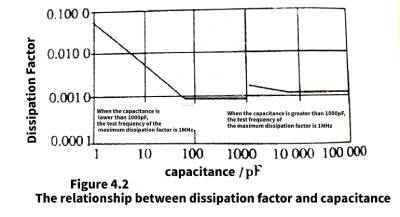
🍑The test conditions for the capacitance of mica capacitors are: the test frequency of the capacitance below 1000 pF is 1 MHz, and the test frequency of the capacitance greater than 1000 pF is 1 kHz. The capacitance tolerance of mica capacitors can be very low, reaching 0.1%, while the general capacitor tolerance is mostly 10% or 2%. Less than 5% is rare. The tolerance of mica capacitors can be so precise, indicating that the stability of mica capacitors is very good, with very little variation with temperature and time.
2.3 Current characteristics
🥭The current characteristic of mica capacitors is one of the most significant features of mica capacitors, and it can often be seen in the data of mica capacitors, the dv/dt parameter that reflects the peak current withstand capability of the capacitor. The dv/dt of mica capacitors can reach more than 100000V/uS; the corresponding current of 1000PF capacitance under the action of 100000/uS voltage change rate is 100A. This is not possible with other dielectric capacitors.
Mica capacitors are usually marked with their allowable rms current in high frequency power applications. Taking the domestic CYG-9 high-power mica capacitor as an example, the rated voltage is 7.5kV, the nominal capacitance is 0.1uF, the working current is 57A at 1MHz frequency, and the current is 80.5A when forced to work at 1MHz frequency for 5 minutes.
2.4 Frequency characteristics
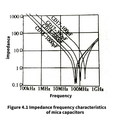
🎈The impedance-frequency characteristics of mica capacitors are very good. Figure 4.1 shows the impedance-frequency characteristics of CDE’s CD17 series mica capacitors. It can be seen from the figure that the resonant frequencies of the mica capacitors are all above 50MHz, that is to say, the mica capacitors all exhibit capacitive characteristics below 50MHz. Not only that, the ESR of this mica capacitor is also very low, less than 0.5Ω, and the 1000pF specification is close to 0.1Ω, which is the lowest among capacitors with various dielectrics.
2.5 Dissipation factor
When the capacity is less than or equal to 82pF, the loss is in the range of 0.01-0.03, when the capacity is greater than 82pF, the loss is below 0.01, and the minimum can be below 0.03. For high-power mica capacitors, the loss factor is slightly larger, and its maximum value is still lower than 0.0015.
2.6 Insulation resistance
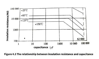
🎉The insulation resistance of mica capacitors is very high, and power mica capacitors can reach (+20±5℃, relative temperature ≤70%) above 8000MΩ; CYT-3 1-1600P encapsulated mica capacitors have insulation resistance of not less than 10000MΩ under normal weather conditions. The relationship between insulation resistance and capacitance of CDE’s mica capacitors is shown in Figure 4.3.
3 Mica capacitor data and main application introduction
3.1 High Power Mica Capacitors
High-power mica capacitors are an important branch of mica capacitors, and are mainly used as vibration capacitors in high-frequency resonant power converters of hundreds of kilohertz or even several megahertz. Compared with ceramic power capacitors, mica capacitors can obtain larger capacitances, while relatively thin
🎄For film capacitors, the low dissipation factor of mica capacitors is more suitable for relatively high operating frequencies.
For high power mica capacitors, the main limiting factor in high frequency applications is the operating current. When the operating frequency is high to a certain extent, due to the combined action of the high-amplitude current flowing through the ESR of the mica capacitor Yuchang and the heating factor generated by the loss factor at high frequencies, many
🌲In case the rated current of the high power mica capacitor will limit the AC working voltage of the high power mica capacitor. The relationship between current and frequency of CDE’s 273 type power mica capacitor is shown in Figure 4.4.
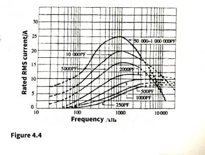
It can be seen from the figure that the rated current of the mica capacitor increases with the frequency at a relatively low frequency. It can also be found through analysis that the current increase does not completely change with the increase of the frequency according to the relationship between the rated voltage and the impedance of the capacitor, but Is slower than this relationship. This shows that when the frequency increases to a certain extent, the factor of cut-off loss cannot be ignored.
🌳For a mica capacitor with a relatively large capacitance, the maximum current corresponding to the frequency is about 1 MHz; while for a relatively small capacitance, it enters a working state similar to “constant current” between 1 and 3 MHz. The higher the frequency of entering the “constant current” state.
For mica capacitors with relatively large capacitance, when the current rises to the highest value, as the frequency continues to increase, the allowable current of the capacitor will decrease with the increase of the frequency, and the higher the frequency, the faster the allowable current decreases. This indicates that the dielectric loss of the mica capacitor becomes the main loss. From the perspective of capacitor application, in general, capacitors should not work in this mode. Therefore, the maximum operating frequency of mica capacitors with relatively large capacitance should not be higher than the maximum allowable current of mica capacitors.
🌴As can be seen from Figure 4.4, mica capacitors with smaller capacitance can work at relatively higher frequencies, for example, mica capacitors with a capacitance below 1000 pF can even work at 1 OMHz. Considering the problem from this point of view, multiple low-capacity mica capacitors can be applied parallel to obtain a relatively high operating frequency.
1.CYG-9 type high power mica capacitor
🌷The domestic CYG-9 high-power mica capacitors are characterized by low dielectric loss, high withstand voltage and stable capacity. They are suitable for the oscillation circuit of high-power wireless motors, and are more suitable for high-frequency welding equipment lines for steel pipes.
Environmental conditions: ambient temperature -45~+60℃, relative humidity below 80%, atmospheric pressure 450~480 mmHg. Vibration frequency 50 Hz, acceleration up to 4 g.
🌹The capacity tolerance is ±5% (J) and ±10% (K).
The capacitor should be able to withstand the test voltage for one minute without breakdown.
🌞Loss factor < ie +20 ± 5 ℃ relative mixing < 70%) should not be greater than 0.0015.
Insulation resistance (+20±5℃, relative humidity≤70%) should not be less than 8000 MΩ.
🌻Capacitor temperature stability is not more than 2%.
The capacitance, rated voltage, working current and short-time working current of CYG-9 high-power mica capacitors are shown in Table 4.1.
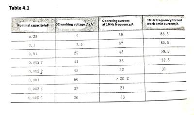
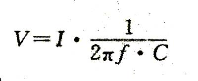
🌸The rms value of the AC voltage allowed at this frequency can be obtained from the rated current at 1MHz.
The obtained value is significantly lower than the rms value of the AC voltage converted from the DC working voltage, indicating that the mica capacitor works in a limited working current state due to the heating caused by the ESR and dissipation factor.
2.CYG4 high frequency high voltage mica capacitor
🌟CYG-4 high frequency high voltage mica capacitors are suitable for communication circuits of broadcasting equipment. The working temperature is -55~1085 ℃; the test voltage of the capacitor is 2 times the DC working voltage; the insulation resistance of the capacitor is not less than 2000 MΩ under normal weather; the tangent value of the loss angle of the capacitor is not more than 0.01 under normal weather conditions.
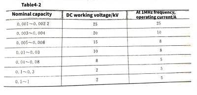
The capacitance, rated voltage and working current data of CYG-4 high frequency and high voltage mica capacitors are shown in Table 4.2.
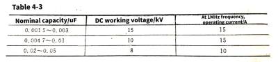
3.CYG-3 High Frequency High Voltage Mica Capacitor
✨CYG3 high frequency and high voltage mica capacitors are suitable for communication circuits of broadcasting equipment. The working temperature is -55~+85 ℃; the test voltage of the capacitor is 2 times the DC working voltage; the insulation resistance of the capacitor is not less than 2000MΩ under normal weather; the tangent value of the loss angle of the capacitor is not more than 0.01 under normal weather conditions. The capacitance, rated voltage and working position current data of CYG-3 high frequency and high voltage mica capacitor are shown in Table 4.3.
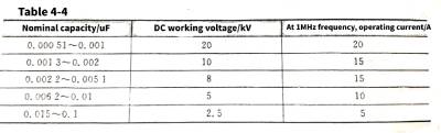
4.CYG-2 High Frequency High Voltage Mica Capacitor
💨CYG-2 high-frequency high-voltage mica capacitors are suitable for communication circuits of broadcasting equipment, and can also be produced according to the special requirements of users. The working temperature is -55~+85 ℃; the test voltage of the capacitor is 2 times the DC working voltage; the insulation resistance of the capacitor is not less than 2000MΩ under normal weather; the tangent value of the loss angle of the capacitor is not more than 0.01 under normal weather conditions.
The capacitance, rated voltage and working current data of CYG-2 high frequency and high voltage mica capacitor are shown in table 4.4.
5.CYG-1 High Frequency High Voltage Mica Capacitor
☔️This product is suitable for communication circuits of broadcasting equipment, and can also be produced according to the special requirements of users. The working temperature is -55~+85 ℃; the test voltage of the capacitor is 2 times the DC working voltage; the insulation resistance of the capacitor is not less than 2000 MΩ under normal climate; the capacitor Under normal climatic conditions, the loss angle tangent value is not greater than 0.01.
The capacitance, rated voltage and working current data of CYG-1 high frequency and high voltage mica capacitor are shown in Table 4.5.

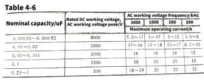
6.CYS-4 type mica capacitor
🌊This product is suitable for DC, AC and pulse circuits and is widely used in electromechanical equipment, broadcasting, communication systems. The ambient temperature is -55~85℃; the allowable deviation of the capacitor is ±5%; the insulation resistance of the capacitor is not less than 5000MΩ, and the insulation resistance of the capacitor is not less than 2000MΩ if it is greater than 0.1uF; under normal weather conditions, the DC voltage of the capacitor is twice the rated value DC working voltage, the effective value of the AC test voltage of the capacitor (50Hz) is the rated DC working voltage; the loss tangent value of the capacitor is not greater than 0.01.
The capacitance, rated voltage and operating current data of CYS-4 mica capacitors at different frequencies are shown in Table 4.6
7.CYS-3 type mica capacitor
💫This product is suitable for DC, AC and pulse circuits and is widely used in electromechanical equipment, broadcasting, communication systems. The ambient temperature is -55~+85℃; the deviation of the capacitor is ±5%; the insulation resistance of the capacitor is not less than 5000MΩ, and the insulation resistance of the capacitor is not less than 2000MΩ if it is greater than 0.1uF; under normal weather conditions, the DC voltage of the capacitor is 2 times the rated DC Working voltage, the effective value of the AC test voltage of the capacitor (50Hz) is the rated DC working voltage; the tangent value of the loss angle of the capacitor is not greater than 0.01.
The capacitance, rated voltage and operating current data of CYS-3 mica capacitors at different frequencies are shown in Table 4.7.
8.CYS-2 type mica capacitor
❄️This product is suitable for DC, AC and pulse circuits, and is widely used in electromechanical equipment, broadcasting, and communication systems. The ambient temperature is -55~+85℃; the allowable deviation of capacitors is ±2%; the insulation resistance of capacitors is not less than 5000MΩ; in normal climates Under the conditions, the DC voltage of the capacitor is twice the rated DC working voltage. The effective value of the AC test voltage of the capacitor (50Hz) is the rated DC working voltage; the tangent value of the loss angle of the capacitor is not greater than 0.01.
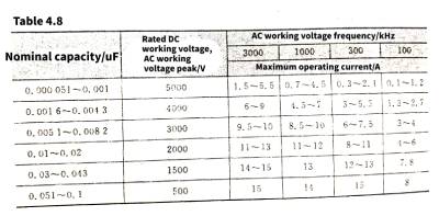
The capacitance, rated voltage and operating current data of CYS-2 mica capacitors at different frequencies are shown in Table 4.8.
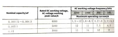
9.CYS-1 type mica capacitor
🥝This product is suitable for DC, AC and pulse circuits and is widely used in electromechanical equipment, broadcasting, communication systems. The ambient temperature is -55~+85℃; the allowable deviation of the capacitor is ±1%; the insulation resistance of the capacitor is not less than 5000MΩ; under normal weather conditions, the DC voltage of the capacitor is twice the rated DC working voltage, and the AC test voltage of the capacitor is valid The value (50Hz) is the rated DC working voltage; the loss tangent value of the capacitor is not greater than 0.01.
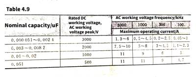
The capacitance, rated voltage and operating current data of CYS-1 mica capacitors at different frequencies are shown in Table 4.9.
3.2 Precision mica capacitors and high temperature mica capacitors
🥦Mica capacitors are not only suitable for high-power, high-frequency, high-voltage applications, but also for high-precision capacitance, high-temperature, and high-reliability applications.
1. CYHM Precision Mica Capacitors
🎇The biggest feature of precision mica capacitors is the small tolerance of capacitance. The main properties of domestic CYHM precision mica capacitors are as follows.
Working temperature: -55~+70℃.
🌄Insulation resistance: ≥10000 MΩ.
Loss tangent: xn--tan0-imd0528b.005.
🌅Capacitance tolerance: 0.1%.0.3%,.0.5%.
2.CYF type mica capacitor
Domestic CYF mica capacitors are mainly used in communication, navigation and other instruments and equipment. They have the characteristics of good performance, small size and high power. ; The test voltage is 2 times the DC working voltage; the tangent value of the loss angle is not greater than 0.015.
3. CVG type high temperature mica paper capacitor
🧬The domestic CVG type high temperature mica paper capacitor is made of 511 mica paper as the main medium and is impregnated with high temperature epoxy resin.
Insulation resistance R>500 MΩ after holding at 200℃ for 1 h; loss tangent value xn--tan0-imd0528b.005; DC withstand voltage meets the requirements; its capacity change rate is <10%; capacitance tolerance: ±2%., ± 5%, ±10%.
4.CYT-3 encapsulated mica capacitor
🎠The domestic CYT-3 type encapsulated mica capacitor has the characteristics of small size, light weight and convenient installation. It is suitable for AC and DC high-frequency oscillation circuits of various electronic equipment, and the capacitance ranges from 1 to 1 6000 pF. The main properties are: the ambient temperature is -55~+100℃; the allowable error of capacitor capacity is ±5%; the insulation resistance is not less than 10000 MΩ under normal climatic conditions; the test voltage or voltage is 2 times the rated DC working voltage; under normal climatic conditions The lower loss tangent value is not greater than 0.01.
4 Vacuum is the basis of containers
🎸The maximum operating frequency of high-power mica capacitors can reach 3 MHz, and even for low-capacitance heavy mica capacitors, the maximum operating frequency will not exceed 10 MHz. If it is used as a high-power capacitor at a higher frequency, the effective value of the current that it allows to flow will drop sharply due to factors such as dielectric loss. At this time, mica capacitors can no longer meet the requirements of high-power capacitors at higher frequencies. Because mica capacitors with excellent dissipation factor can no longer meet the requirements, capacitors with other dielectrics can not meet the application requirements. Capacitors seeking to meet the requirements must be “without” the medium, that is, a vacuum. Since there is no “substance”, there is no fatal dielectric loss caused by the action of the commercial frequency, which is the fundamental reason for the existence of vacuum capacitors.
4.1 What is a vacuum capacitor
🎭As the name suggests, a vacuum capacitor is a capacitor that uses vacuum as a medium. The electrode group of this capacitor is made of high-conductive oxygen-free copper tape, and a group of concentric cylindrical electrodes formed by extending through a set of high-precision molds are sealed in a vacuum container. Therefore, its performance is stable and reliable, and it is not easy to produce arcing, corona and other phenomena.
4.2 Classification of Ceramic Vacuum Capacitors
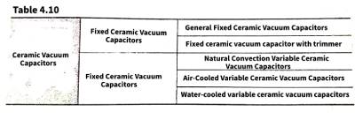
🤹The basic structure of vacuum capacitors is mainly electrodes and isolation electrodes combined with a vacuum-sealed insulating casing. In order to ensure good low-loss characteristics at high frequencies, the insulating casing can be glass or ceramic. Since glass is fragile, after solving the ceramic-metal sealing problem, ceramic insulating housings are used in most cases. The classification of vacuum capacitors is shown in Table 4.10.
4.3 Naming method
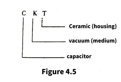
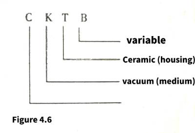
🥇According to international regulations, the model name code of vacuum capacitors is composed of the first letter (uppercase) of Chinese Pinyin, except that the capacitor is represented by C. Take ceramic vacuum capacitors as an example, as shown in Figure 4.5 and Figure 4.6.
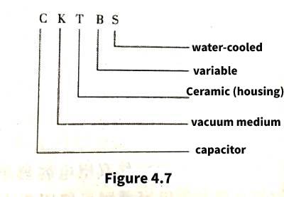
🍹Fixed ceramic vacuum capacitors with fine-tuning and air-cooled variable ceramic vacuum capacitors are not produced by any manufacturer in my country. Water-cooled variable ceramic vacuum capacitors are still in their infancy in my country, and there is no national standard for the naming method. You can refer to the nomenclature of vacuum capacitors with fixed capacitors, and refer to the naming method of vacuum capacitors with adjustable capacitance abroad to name the vacuum capacitors with adjustable capacitance. capacitor, as shown in Figure 4.7.
5 Application fields and characteristics of vacuum capacitors
5.1 Application fields of vacuum capacitors
🍪(1) Broadcast communication equipment: vacuum capacitors are used as components for tuning, coupling, filtering, neutralization, and DC blocking on medium-wave, short-wave, and ultra-short transmitters.
(2) Semiconductor manufacturing equipment: deposition and etching equipment for plasma.
🥙(3) High-frequency industrial equipment: used for high-frequency dielectric heating and welding, etc.
(4) Medical equipment; medical analyzers and therapeutic instruments, etc.
🧁(5) High-energy physics: high-energy particle accelerators, etc.
(6) Power equipment: used for dielectric loss test equipment.
5.2 Characteristics of vacuum capacitors
🎂Compared with other dielectric capacitors, vacuum capacitors have the characteristics of high withstand voltage, small size, low loss, stable and reliable performance. The unique features are as follows.
(1) The rated voltage is high. Due to the high dielectric strength of vacuum, coupled with the characteristics of dust-proof pollution and moisture-proof, vacuum capacitors have a large rated voltage value for a certain size and capacity, and the highest voltage can reach hundreds of thousands of volts.
🥗(2) The loss is small. High rated current. Since the capacitor adopts a vacuum dielectric, a low-loss insulating shell and an oxygen-free copper electrode structure,
In the case of general convection cooling, even at a very high frequency, a large RF current can be passed. If a special water cooling structure is adopted, the RF current can reach thousands of amps.
🍹(3) Save space. For a given capacitance and voltage rating, vacuum capacitors occupy the smallest space.
(4) Wide adjustment range. The ratio of maximum capacity to minimum capacity is as high as 150:1, ranging from a few picofarads to several thousand picofarads, making it an ideal element for a wide tuning range.
⭐️(5) Self-healing ability to overvoltage: vacuum capacitors can withstand instantaneous overvoltage. With the disappearance of electric isolation, the capacitor automatically restores its original insulating ability, while for other capacitors, it will cause permanent damage. .
(6) Ability to work at high altitudes. Vacuum sealing can make vacuum capacitors work in high altitude areas without degrading their characteristics, while other dielectric capacitors may be due to the presence of gas inside the capacitor. As the gas density (pressure) decreases, the general insulation spacing will no longer meet the insulation requirements. Arc discharge causes short circuit problems, therefore, other dielectric capacitors have altitude or air pressure limitations.
🌾(7) Since the vacuum capacitor is made of high-quality oxygen-free copper electrodes, the resistance is extremely low. Therefore, the equivalent series resistance of the vacuum capacitor is also extremely low. For example, the ESR of vacuum capacitors produced by JENNING is only tens of microohms, which is the lowest among capacitors with various dielectrics. The main data of PV4-500 vacuum capacitors produced by JEN-NING are shown in Table 4.11.
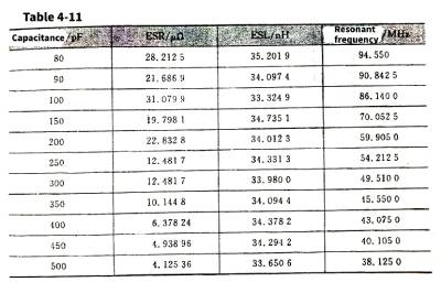
(8) It can be seen from Table 4.11 that the equivalent series inductance of vacuum capacitors is relatively large due to their large size (due to high voltage), which is significantly larger than that of laminated ceramic capacitors, and is basically similar to that of high-power high-voltage ceramic capacitors.
6 The structure of the vacuum electric device
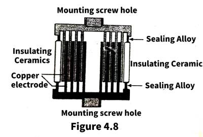
🌺Vacuum capacitors can be divided into two categories in terms of structure, vacuum capacitors with fixed capacitance and vacuum capacitors with adjustable capacitance. The cross-sectional structure of a vacuum capacitor with fixed capacitance is shown in Figure 4.8.
The structure of the vacuum capacitor with fixed capacitance is relatively simple, and the two concentric electrodes can be fixed with an insulating ceramic. In order to ensure that the thermal expansion coefficient of the metal and the insulating ceramic is the same, it is necessary to use a transition sealing metal that can be in close contact with the ceramic and has the same thermal expansion coefficient between the electrode and the insulating ceramic. For example, Dumet alloy needs to be used between glass and metal to ensure air tightness sex.
🍂The structure of a vacuum capacitor with adjustable capacitance is shown in Figure 4.9.
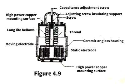
Different from the vacuum capacitor with fixed capacitance, the vacuum capacitor with adjustable capacitance needs to adjust the capacitance by moving the relative position of the two electrodes, and at the same time ensure the airtightness of the vacuum capacitor. At this time, the bellows can well solve the contradiction between the displacement of the electrode and the air tightness.
🍀The screw of the adjusting capacitor is fixed on the movable electrode, and the position of the movable electrode is raised and lowered by adjusting the screw to realize the adjustment of the capacitance.
7 General technical conditions of vacuum capacitors
(1) Maximum allowable operating temperature. The maximum allowable operating temperature of the capacitor is 120°C
🍄(2) Cooling method. Unless otherwise required, all are natural air convection.
(3) The installation location is arbitrary.
🍡(4) Temperature coefficient. The temperature coefficient of the capacitor is less than or equal to 0.001.
(5) The rotation direction of the increase of the capacitance of the variable capacitor is the counterclockwise direction.
🍧(6) Collision. The peak acceleration is 100 m/, the pulse duration is 16ms; the number of collisions is 10,000.
(7) VIBRATION. The vibration direction is specified by the product standard; the frequency range is 5~55Hz; the amplitude value is 20 m/or as specified by the product; the duration is specified by the product standard.
8 Main technical parameters and analysis of vacuum capacitors
🍨(1) Capacitance. Fixed capacitor: When the nominal capacitance value is greater than 50 pF, the allowable deviation is ±5%; when the nominal value is 5~-50 pF, the allowable deviation is ±10%. Variable capacitor: the maximum capacity tolerance is ±5%; the minimum capacity is less than or equal to the nominal value.
(2) Peak test voltage. The peak test voltage refers to the maximum value of the power frequency voltage that can be applied to the capacitor to produce a breakdown (in the form of internal or external flashover). The test of the capacitor at this voltage is a means of determining the overall condition of the capacitor.
🧆(3) RF working voltage. The RF working voltage refers to the maximum value of the RF peak voltage that can be continuously applied to the capacitor without affecting its ability to withstand instantaneous overvoltage. It is usually 60%~70% of the peak test voltage rating, which is a safe value recommended when selecting capacitors.
(4) Maximum RF current. The maximum RF current refers to the RF current allowed to pass through the capacitor at the maximum capacity and a certain frequency in the working power, which is mainly limited by the current-carrying capacity of the electrode.
🏡The relationship between the current and frequency of a vacuum capacitor is shown in Figure 4.10.
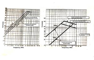
It can be seen from the figure that when the current flowing through the capacitor does not reach the relatively low frequency of the maximum current value, the current flowing through the capacitor increases with the frequency, which does not strictly conform to the relationship between the voltage, current, capacitance and frequency of the capacitor. Indicates that in this frequency band, the state of the capacitor is limited by the maximum RF peak voltage; when the frequency rises, the current flowing through the capacitor reaches the rated limit. The state of the capacitor becomes limited by the power loss and enters the constant power operation state, and it can be seen that the limit value of the current decreases slightly with the increase of the frequency, indicating that there is the effect of the loss factor.
🚴♂️In the frequency band where the current increases with frequency, the current flowing through a capacitor with a large capacitance is larger than that flowing through a capacitor with a small capacitance, which is in line with the relationship between the current flowing through the capacitor and the capacitance.
The maximum working current of vacuum capacitors is different under different cooling methods. In the state of water cooling, the current that vacuum capacitors can withstand is larger than that of natural convection air cooling.
🏊♀️It can also be seen in Figure 4.10 that the vacuum capacitor has a maximum operating frequency limit, mainly limited by the resonant frequency of the vacuum capacitor.
The optimum operating frequency of a vacuum capacitor should be at its allowable peak current.
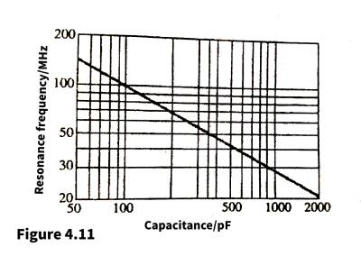
🤽♀️(5) Spectral vibration frequency. Due to the existence of the equivalent series inductance, the vacuum capacitor also has the problem of resonant frequency, that is, the vacuum capacitor exhibits an inductive characteristic when the resonant frequency is above the resonant frequency, so the actual working frequency of the vacuum capacitor must be lower than the resonant frequency. Figure 4.11 shows the relationship between the resonant frequency of a vacuum capacitor and the capacitance.
(6) Dielectric loss. The dielectric loss of the capacitor is less than or equal to 0.01. The loss factor of vacuum capacitors comes from the ESR and dielectric loss of vacuum capacitors, as well as losses such as eddy currents generated on electrodes by high-frequency electromagnetic fields.
🏌️(7) DC leakage current. The DC leakage current of the capacitor is not more than 15uA. The leakage current of vacuum capacitors comes from the sealed case, and the vacuum part generally does not generate leakage current.
(8) Rotation torque (for variable capacitors). The torque of the capacitor should comply with the product standard.
9 Parallel connection of vacuum capacitors
🏇Due to the larger the capacitance; the lower the resonant frequency of the vacuum capacitor. Therefore, in order to obtain a relatively high operating frequency, two or more vacuum capacitors can be selected in parallel to obtain the required capacitance value. Since vacuum capacitors need a relatively long line or loop in parallel, they will enclose a relatively large space, and there must be a relatively large additional inductance in order to average this additional inductance.
On each capacitor, the influence of lead parasitic inductance needs to be considered in parallel connection. The circuit connection structure to be used is shown in Figure 4.12.
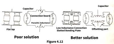
⛹️The easiest way is to connect the vacuum capacitors in parallel with flat straps, but this is not the best solution. The reason is that the flat lap joint will generate a relatively large additional parasitic inductance, which will reduce the resonant frequency of the vacuum capacitor. To avoid this problem, low-inductance slot straps can be used in parallel with vacuum capacitors. In this way, the space enclosed by the straps and vacuum capacitors can be reduced, that is, the additional parasitic electric shock can be reduced.
10 Cooling Methods of Vacuum Capacitors
🤸Temperature limits the maximum power a vacuum capacitor can deliver. The higher the current applied to the vacuum capacitor, the more heat is generated, which causes the temperature inside and on the surface of the capacitor to increase. For glass and ceramic capacitors, the maximum maximum temperature (maximum allowable temperature) standard follows the following principles, the maximum temperature of glass vacuum capacitors does not exceed 85 ℃, and the maximum temperature of ceramic vacuum capacitors does not exceed 125 ℃. Therefore, for capacitor applications, cooling measures are essential, maintaining a suitable temperature while allowing the capacitor to reach the maximum current (maximum ripple current).
For capacitor cooling and heat loss, there are four standard guidelines below, which include water cooling, conduction cooling, forced air cooling, and convection cooling.
🤾♀️Water cooling is the most effective of the four methods. It cools from the inside of the capacitor, using precise pressure to press water from the bottom of the capacitor to keep the inside of the capacitor cool. For capacitors in ceramic envelopes, this is required. method is the most commonly used
Conduction cooling also uses water to cool the capacitor, but in a different way, the capacitor can be equipped with a heat sink or a cold rail device to achieve the purpose of cooling the components through the loss of heat.
🏂JENNING developed a cold sink flange that clamps a water jacket on the outside to cool the capacitor from the outside.
The third method is forced air cooling, which uses a fan to blow air through the product. Although it can play a role in stabilizing the temperature, this method does not guarantee that there is no pollution. The surrounding environment must be considered when using this type of cooling.
🎿The final cooling method is convection cooling, which allows the capacitor to cool naturally. Vacuum capacitors are usually placed in a ventilated room so that the capacitors can have sufficient contact with the air. The room in which the capacitors are placed allows air to circulate freely, allowing the components to automatically find (temperature) equilibrium in their surroundings. This allows the part outside the capacitor to cool, but this does not directly affect to the interior pedestals or metal bottom plates (interior bellows Or plates sets). Although not as effective as water cooling and forced air cooling, convection cooling is also widely used.
In order to achieve maximum current (maximum ripple current) and longest life, cooling measures are extremely important for capacitors. JENNING provides special cooling products to ensure the best performance of capacitors.
11 Additional Notes for Vacuum Capacitors
11.1 Storage of vacuum capacitors
🧩(1) Capacitors should be stored in conditions; the axis is placed vertically, and the environment is clean and dry.
(2) Capacitors are stored for more than three months, and high-voltage conditioning should be carried out to ensure the withstand voltage capability of the capacitors.
🎺(3) When the water-cooled capacitor is under high voltage, it should be ensured that the water in the capacitor is clean.
(4) The transportation of vacuum capacitors should use the original packaging as much as possible, and the capacity of variable capacitors should be adjusted to the minimum and the rotating screw should be adjusted back 3 to 4 turns.
11.2 Voltage test of vacuum capacitors
🎲(1) The AC voltage test of the capacitor should be carried out under the AC voltage of 50 Hz/60 H. Before the test, it should be ensured that there should be no water vapor, oil and other dirt on the wall of the porcelain tube to prevent external breakdown. Adjust the variable capacitor to the maximum capacity end. The test voltage is the peak test voltage.
(2) For the DC voltage test of the capacitor, it should be ensured that there should be no water vapor, oil pollution, etc. on the wall of the ceramic tube before the test, and the variable capacitor should be adjusted to the maximum capacity end. The DC voltage test should be carried out after the AC test is qualified. The test voltage is the peak working voltage.
🚀Note: After the DC test, the capacitor must be fully discharged before the next operation, the capacitor will have some load current after the DC test, which will be very dangerous.
11.3 Installation of vacuum capacitors
(1) The capacitor parameter test should be carried out before installation to ensure that the product is qualified and the appearance of the capacitor is clean.
🛶(2) The cooling method of the capacitor is determined by the RF current passing through the capacitor.
(3) One end of the capacitor electrode must be connected with a flexible, short and wide copper tape.
⛵️(4) During the installation process, the capacitor should avoid the effect of torsion and bending force to prevent the deformation of the ceramic and metal seal,
11.4 Maintenance of vacuum capacitors
🚢Under normal circumstances, vacuum capacitors do not require much maintenance. Capacitors need to be kept away from dust. To prevent dust accumulation, keep the environment dry. Unglazed porcelain cases can be cleaned with detergent and clean water. The rotating screw should be regularly lubricated with oil or special grease.
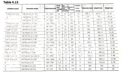
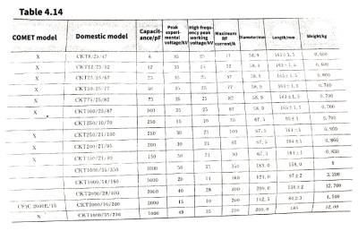
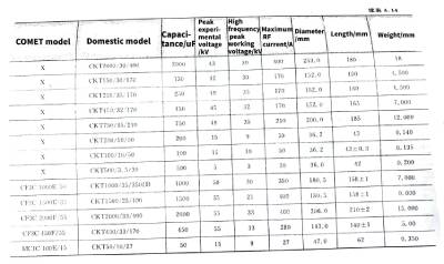
12 Data Analysis and Substitution of Vacuum Capacitors at Home and Abroad
🌌The data and comparison table of the main vacuum capacitor models at home and abroad are shown in Table 4.12~Table 4.15.
Mica-capacitors-and-vacuum-capacitors.jpg)
Mica-capacitors-and-vacuum-capacitors.jpg)
Mica-capacitors-and-vacuum-capacitors.jpg)
Mica-capacitors-and-vacuum-capacitors.jpg)
Mica-capacitors-and-vacuum-capacitors.jpg)