1 Application of large-capacity ceramic capacitors in general bypass
1.1 The role of bypass capacitors
🍏Bypass capacitors are usually connected in parallel across the power supply of a circuit unit (such as an IC) to reduce the power supply as much as possible over the entire operating frequency band or the frequency band where the circuit may be affected. Keep the positive reactance level at a tolerable level to prevent power transmission. Harmful coupling. For the lower frequency band, the electrolytic capacitor of the regulated power supply can provide a very low impedance, but the aluminum electrolytic capacitor will start or will begin to transform into inductive when it exceeds 50kHz, and it cannot maintain the low impedance of the higher frequency band, and from the regulated power supply There is usually a long distance between the output end and each sub-circuit (such as several centimeters to more than ten centimeters is common), its parasitic inductance may reach 1uf, its inductive reactance at 50kHz is 0.314Ω, plus the impedance of the rectifier filter capacitor and The power trace resistance of the circuit board, the power output impedance seen from each sub-circuit to the power supply will be more than 1Ω, and it may reach several ohms or even 10Ω at a frequency of 500kHz. For higher frequencies would be unthinkable. Such power supply impedance is easy to produce harmful power coupling (such as parasitic oscillation or self-excitation of the amplifier circuit, false logic level of the digital circuit at high frequency, inaccurate reference power supply, etc.), and the impedance of 1UF or 0. lUF is at high The frequency is easily below 1Ω. So usually a better solution is to connect ceramic capacitors in parallel across the power supply of each sub-circuit (eg, each IC) to reduce the impedance in the high frequency band of the power supply of each sub-circuit. This is often referred to as the “rule” – large capacitors filter low frequencies, and small capacitors filter high frequencies, but a good large-capacity capacitor can filter out high-frequency ripple quite well, but it is customary to use the frequency in general applications. A misunderstanding caused by ordinary aluminum electrolytic capacitors with poor characteristics.This is the applications of ceramic capacitors.
🍎Another function of the bypass is AC bypass (short circuit), decoupling capacitor, (again short to AC) of the DC bias circuit.
🍐The bypass capacitor has no special requirements on the loss factor. In the bypass application, the bypassed circuit does not generate a high ripple current. Even if the bypass capacitor has a high loss factor, it has no effect on the bypass function of the circuit. As long as the bypass capacitor is not dissipating heat. At this time, ceramic capacitors will be the best choice, and the reason is that it has the lowest cost. If the bypassed circuit may generate a high ripple current (such as the power of the class D power amplifier and the bypass of the power supply), it is necessary to consider the heating caused by the ripple current that the bypass capacitor can withstand and select the capacitor appropriately type.
1.2. Large-capacity ceramic capacitors improve power frequency characteristics
🍊The impedance characteristics of a 100UF aluminum electrolytic capacitor in parallel with a 1UF ceramic capacitor are shown in Figure 3.75.
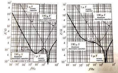
🍋The left picture is the characteristic curve at normal temperature, and the right picture is the characteristic curve at -25℃. The thick solid line in the figure is the impedance-frequency characteristic curve of two capacitors in parallel, the thin line on the left in the figure is the impedance-frequency characteristic curve of the ceramic capacitor, and the thin line on the stone edge is the impedance-frequency characteristic curve of the electrolytic capacitor. As can be seen from the figure, electrolytic capacitors with large capacitance have very low impedance in low frequency bands, while ceramic capacitors can have low impedance in frequency bands beyond the reach of electrolytic capacitors. Applications of Ceramic Capacitors:The combination of the two can obtain a wide frequency range. Ideally low impedance.
🍌Bypass capacitors for high-frequency high-power circuits need to bypass large “high-frequency AC” load currents caused by the load, therefore, bypass capacitors not only need to have low ESR, but also have low dielectric frequency losses.
🍉Not only that, the volume of ceramic capacitors is very small, the leaded ceramics with 0.1~luF capacitance is only 0.2in between the pads of the container, and the 0805 package of laminated capacitors is even smaller, and the soldering size is only 2mm on the printed circuit board. Components and wiring are easy.
🍇If you choose a ceramic capacitor with a larger capacitance (such as 10uF, 22UuF or even 47uF, 100uF), it can completely replace the tantalum electrolytic capacitor.
🍓In general IC application guidelines, tantalum electrolytic capacitors are recommended for bypass capacitors where performance requirements are relatively high. Tantalum electrolytic capacitors are recommended in applications where operating temperatures are high and long lifetimes are required, such as DC/DC power modules.
🍈When applying electrolytic capacitors, it should be noted that electrolytic capacitors are polarized and cannot be used in reverse polarity.
1.3 Other bypass applications
🍒Another function of the bypass capacitor is the AC bypass (short circuit) of the DC bias circuit, and the decoupling capacitor (or short circuit to the AC). In transistor amplifiers or similar circuits, in order to reduce the AC impedance of the transistor emitter resistor, a capacitor is connected in parallel across the resistor. For low frequency circuits, aluminum electrolytic capacitors are usually used, and 0.01uF can be used for medium and high frequency circuits.
🍑The second class of low-cost ceramic dielectric capacitors, taking the intermediate frequency amplifier as an example, the capacitive reactance of the 0.01uF capacitor is 34.2Ω at 465kHz, which is 1/30 of the 1KΩ resistance. If a 0.1uF capacitor is used, the capacitive reactance is reduced to 3.42Ω , equivalent to a short circuit for a 1KΩ resistor. In the power supply decoupling circuit of some high-frequency circuits (such as the decoupling circuit of the bias power supply of the pre-stage part of the split device transistor amplifier in the past), the method of decoupling the ceramic capacitor is also used. The above circuit is shown in Figure 3.76, C2 and C4 are the bypass capacitors for the power supply of the pre-stage circuit and the bypass capacitors for the emitter resistance of the post-stage circuit respectively. Since the circuit in Figure 3.77 is a small-signal circuit, the “AC” current of the bypass is very small. Therefore, it is not necessary to consider the heating problem caused by the loss factor of the capacitor due to the dielectric loss. It is the most economical to choose a cheap ceramic capacitor. Of course, this method of decoupling the bias supply with relatively small ceramic capacitors can also be used in similar circuits.
🥭Ceramic capacitors can also be used for the input, output, and interstage coupling capacitors of AC amplifiers. The large coupling capacitors in Figure 3.77 are different from the requirements for bypass capacitors. The coupling capacitors require that the leakage current of the capacitors is as small as possible. Therefore, it is better to use ceramic capacitors with low leakage current as coupling capacitors in demanding occasions.
2 Application of large-capacity ceramic capacitors in bypassing and high-frequency rectification and filtering of switching power loads
🍍In the application of power frequency rectification and filtering, aluminum electrolytic capacitors should be irreplaceable, especially when power frequency rectification and filtering are above 100V. In this working state, a large capacitance is required to reduce the power frequency capacitive reactance as much as possible, so as to better filter the power frequency ripple and the resulting high-order harmonics. Applications of Ceramic Capacitors:Not only that, the capacitor for power frequency rectification and filtering also plays a role in energy storage, because when the capacitor is input to the filter, the rectifier is only turned on for 2~-3 ms per half power cycle, and the remaining ~8 ms is required for negative power. The electric energy of the power supply is provided by the filter capacitor. The low-voltage rectification often requires thousands or even hundreds of thousands of microfarads. The high-voltage rectification of the direct rectification of 220 V or 380 V power supply also requires hundreds or even thousands of microfarads, which is also the reason for the need for large-capacity capacitors. At this time, the role of aluminum electrolytic capacitors is irreplaceable.
🥝In applications that require large-capacity capacitors such as the bypass of switching power loads and high-frequency rectification and filtering, the usual habit is to immediately think of aluminum electrolytic capacitors. If the performance of aluminum electrolytic capacitors cannot meet the requirements, turn to tantalum electrolytic capacitors. Nowadays, there are many types of capacitors that can complete high-frequency rectification and filtering functions, and there are various options. For example, in applications with higher requirements, aluminum and tantalum polymer electrolytic capacitors with lower ESR can also be considered.
🍅It is undeniable that large-capacity ceramic capacitors should be a good choice when the price restricts the product and requires the use of higher-performance capacitors. For high-frequency rectification and filtering during switching power conversion of 100 kHz or above, the capacitive reactance of the capacitor is already very small.
🍆For example, the capacitive reactance of 100UF capacitor at 100kHz is 15.9 mΩ, while the lowest ESR of 100UF aluminum electrolytic capacitor with low ESR is about 400 mΩ, and the ESR of 1000UF low ESR aluminum electrolytic capacitor is 70m.Ω 100UF standard tantalum electrolytic capacitor The minimum ESR is about 250mΩ, even the minimum ESR of ultra-low ESR tantalum electrolytic capacitors is about 60mΩ, and the minimum ESR of aluminum polymer electrolytic capacitors is at least 20mΩ, which is higher than 15.xn--9m-fcc. At this time, electrolytic capacitors are more like resistors than capacitors at such high frequencies. The ESR of the first 10 UF ceramic capacitor is only 0.003Ω (ie 3 mΩ), which is significantly lower than the capacitive reactance of 100UF (15.9 mΩ). At this time, the role of the capacitor still plays an absolute leading role. For the 3rd, 5th, and 7th times of the square wave of 100kHz, the capacitive reactance is correspondingly reduced to 5.xn--3m-fcc, .3.xn--2m-fcc, and .2.xn--3m-fcc, which can also be capacitive characteristics. Low impedance in the frequency band above 20 kHz and below 5 MHz can be obtained if the ESR-reducing electrolytic capacitor is connected in parallel with a large-capacitance ceramic capacitor.
🥦The basis for the scientific selection of high-frequency rectifier filter capacitors is the allowable ripple current of the filter capacitor, and the allowable value of the ripple current is determined by its ESR (p=.) in most cases. For the same size package, it is allowed to When the temperature rise is the same, the smaller the ESR, the larger the allowable ripple current value. For example, the minimum ESR of standard tantalum electrolytic capacitors is 250 mΩ, while the ESR of large-capacity ceramic capacitors is generally 10~-30 mΩ. The allowable ripple current will be ~ times that of tantalum electrolytic capacitors, that is, 3.16~5.47 times. The allowable ripple current of standard tantalum electrolytic capacitors is 066 A, and the allowable ripple current of ceramic capacitors will reach their corresponding multiples of 2.08A and 3.6A.
2.1 Power supply bypass capacitors as switching power loads
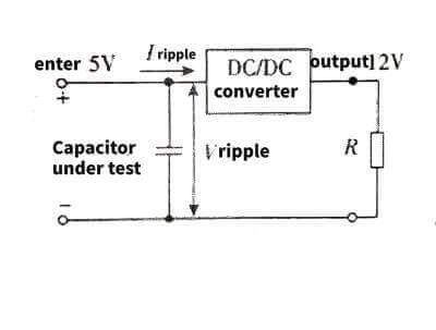
🥬For the power bypass of the switching power load, the test results given by the domestic torch capacitor are as follows. Applications of Ceramic CapacitorsDC/DC converter: 5 V input, 12 V output, switching frequency 450 kHz, input current 0.34 A, output current 0.12A. The schematic diagram of the experimental circuit is shown in Figure 3.78. A 100 UF aluminum electrolytic capacitor, a 33 UF tantalum electrolytic capacitor and a 2.2 uF ceramic capacitor are connected in parallel at the power input end of the DC/DC converter. Test the ripple voltage and ripple current at the input end of the DC/DC converter as shown in the table.
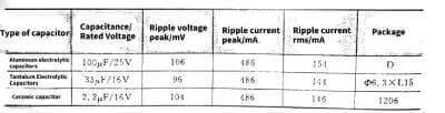
🥒This test result shows that high-capacitance ceramic capacitors are effective in high-frequency rectification and filtering applications, especially at frequencies above 300kHz.
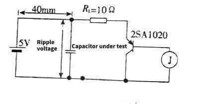
🥗Large-capacity ceramic capacitors have a good suppression effect on power supply voltage transients caused by transient loads. The test circuit is shown in Figure 3.79. The length of the wire from the power supply to the load (that is, the test point) is 40cm. This length is common between the power supply circuit and the load circuit, which is equivalent to connecting a wire of at least 100nH in series between the power supply and the load. This “in-series” inductance will have a large effect on the supply voltage on the load side. The test results are shown in Figure 3.80.
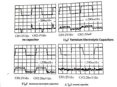
⭐️When there is no capacitor, the peak-to-peak voltage ripple of the test point reaches 2.6. This peak-to-peak voltage will cause logic errors to digital circuits, and the computer may have program errors or even crash; after the capacitor is connected, due to load transients The resulting power supply changes will be effectively suppressed. After the 47UF aluminum electrolytic capacitor is connected to the power supply end of the load, the peak value of the ripple voltage is 25m. After the 10UF tantalum electrolytic capacitor is connected, the peak-to-peak value of the ripple voltage is 25m, and the ripple voltage when the 4.7UF ceramic capacitor is connected is reduced to about 5 mV. Obviously, the ceramic capacitor is the most effective among the three capacitors, and it is also the capacitance the smallest.
🌟If the high-capacity ceramic capacitors are compared with ultra-low ESR tantalum electrolytic capacitors and polymer electrolytic capacitors (the lowest ESR can reach 5 mΩ) in high frequency rectification and filtering, if the above test results can still be obtained, it will have better performance. widely used. For higher capacitance and lower ESR, several laminated ceramic capacitors can also be combined, as shown in Figure 3.81.
✨The ESR of such a 22 UF on-chip ceramic capacitor is about 10 mΩ. For example, three parallel capacitors can obtain a capacitance of 68 UF, and the ESR can be reduced to below 3.5 mΩ, which is much lower than the 10 mΩ of a single 68 UF. Similarly, the combination of more on-chip ceramic capacitor monomers (whether it is an already combined product or a later combination of the user) can both increase the capacitance and greatly reduce the ESR, both of which are high-frequency The performance required for rectification and filtering.
2.2 Laminated ceramic capacitors are used as output filter capacitors for high frequency switching power supplies
💥The requirements for completing the high-frequency output rectification and filtering functions of the switching power supply are considered comprehensively from the aspects of capacitance, cost, high temperature resistance, low ESR, high ripple current, and good high-frequency characteristics. A laminated ceramic capacitor is probably the best choice. The fundamental reason is that chip ceramic capacitors can achieve very high capacitance, such as 1210 package can reach 100 UF, while the ESR is only 10 mΩ. It can withstand high temperatures of 125 ° C, as the price of ceramic chip capacitors is getting lower and lower. , the selection of on-chip ceramic capacitors will become more and more widespread.
🌈The most widely used laminated ceramic capacitors are DC/DC modules. DC/DC modules have much looser component price requirements than AC/DC, and high temperature requirements make it impossible to apply aluminum electrolytic capacitors, and the rest is to compete with tantalum electrolytic capacitors. Both laminated ceramic capacitors and tantalum electrolytic capacitors are capacitors with excellent performance, and the ESR of laminated ceramic capacitors is much lower than that of tantalum electrolytic capacitors. When the same volume is used, laminated ceramic capacitors will allow a higher ripple current to flow.
☀️Another advantage of laminated ceramic capacitors is that they can be stacked to form multi-chip ceramic capacitors, which not only solves the problem of capacitance retention, but also solves the problem of large-sized laminated ceramic capacitors during thermal cycling. The problem of fracture caused by the different thermal expansion coefficients of the board is greatly reduced due to the stacking method of multiple laminated ceramic capacitors, which greatly reduces the area occupied by the circuit board, and at the same time, the resulting parasitic inductance is greatly reduced.
💦It should be noted that due to the extremely low ESR of the laminated ceramic capacitor, compared with the tantalum electrolytic capacitor circuit, there may be a larger voltage overshoot when the load is abruptly changed. That is, the stability is slightly worse.
🪐For AC/DC converters with low switching frequency (such as 50~100kHz), the output filter capacitor needs a relatively large capacitance to support the “stable” of the output voltage, so aluminum electrolytic capacitors are mostly used. However, the high frequency performance of aluminum electrolytic capacitors is far inferior to that of laminated ceramic capacitors. You can make full use of the advantages of both and avoid disadvantages. Connecting laminated ceramic capacitors in parallel with the pins of the output filter capacitor or at the output end will effectively reduce the peak voltage during switching.
2.3 Prevention and control of electrolytic capacitor explosion of computer motherboard
🌺In the media, we often see recalls caused by the explosion of the electrolytic capacitors on the motherboard of a certain brand of computer. In practical applications, it is often seen that the computer fails due to the explosion of the electrolytic capacitor on the motherboard after the computer has been used for several years. It can be said that the explosion of the electrolytic capacitor of the computer motherboard or the loss of capacitance due to the drying of the electrolyte is the most common failure in the application process.
🌸So, why do computer motherboards use electrolytic capacitors? Because computer motherboards require various voltage levels, DC/DC converters are required to convert the power supply voltage into the required voltages, and the output of DCIDC converters requires filter capacitors. Since the computer is a commercial electronic product, it is necessary to pursue the price as low as possible, so the selection of electrolytic capacitors has become an inevitable choice.
🌼If three electrolytic capacitors with a capacitance of 1000UF are used, how much current can such electrolytic capacitors withstand? ESRO.xn--18-fcc.615mA rated ripple current. The electrolytic capacitors of the computer motherboard will be impacted by a much higher current than this data, here is the ripple current generated by the DC/DC converter, and a larger part is the high frequency ripple current generated by the computer motherboard circuit, these ripples If the current converges in the electrolytic capacitor, the electrolytic capacitor will inevitably heat up. If it is overheated, it will burst. If it reaches the bursting level, the electrolyte will dry up for a long time. This is the electrolysis of the computer motherboard that has been used for several years. The reason why the electrolyte does not flow out after the explosion-proof valve of the capacitor is opened.
🌻When encountering such problems, the computer can work as long as the electrolytic container is replaced. Applications of Ceramic Capacitors:However, since the replaced electrolytic capacitor may not be as good as the original electrolytic capacitor, the time required for re-exploding may be shorter. In order to solve this problem, in addition to replacing the electrolytic capacitors, two 10 UF 1206 packaged laminated ceramic capacitors can be connected in parallel on the pin pads of each electrolytic capacitor, which can be said once and for all. The reason is very simple. The ESR of a 10 UF 1206 packaged laminated ceramic capacitor is less than 10mΩ, and the ESR of two parallel capacitors is only 5 mΩ, which is much lower than the low ESR electrolytic capacitor of 1000UF. In this way, most of the high-frequency ripple current Will flow into the laminated ceramic capacitor. The burden of electrolytic capacitors will be greatly reduced.
🌝In order to prevent the electrolytic capacitor of the main board from bursting one day in the future, if you buy a newly purchased computer with an assembled machine, you can solder the purchased computer on the pin pads of the electrolytic capacitor on the main board like an audiophile “grinder”. On-chip ceramic capacitors in 10 UF 1206 package. So you can use it with confidence.
🌞The last question, how much is the 10 UF 1206 package laminated ceramic capacitor? In 2005, I bought 1000 X7R dielectric 1206 package capacitors in the Beijing electronic market for only 200 yuan, an average of 0.2 yuan per piece. If you install 6, you only spend 1.2 yuan.
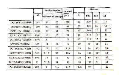
The data of SYFER small high-voltage and large-capacity laminated ceramic capacitors are shown in Table 3.18 and Table 3.19.
Table 3.18 is as follows
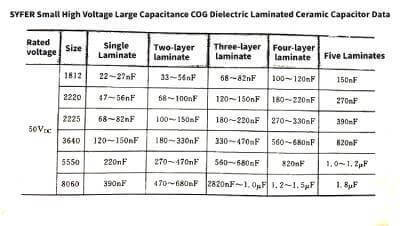
3.18Applications-of-Ceramic-Capacitors.jpg)
Table 3.19 is as follows
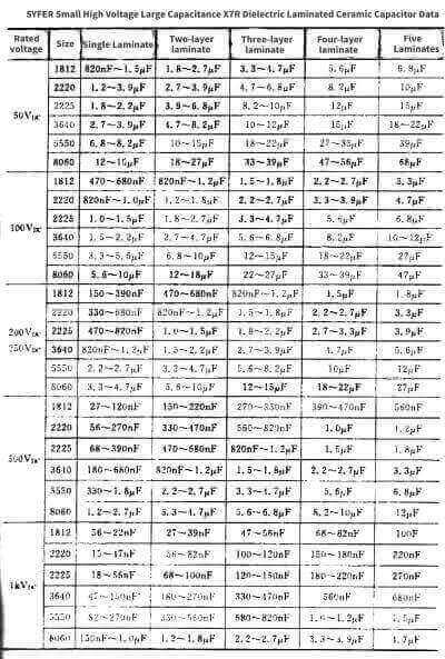
3.19Applications-of-Ceramic-Capacitors.jpg)
2.4 Used for high frequency power oscillation and high frequency power bypass
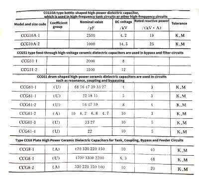
🎄There is a special type of ceramic capacitors – high frequency power ceramic capacitors. It is mainly used for high-frequency power resonance (such as industrial high-frequency heating, high-frequency oscillation of high-frequency wireless transmission, etc.) high-frequency resonance tank circuit, bypass of high-frequency circuit power circuit, coupling and feeding of high-frequency circuit, etc. High-frequency power circuits are characterized by high frequency, which can range from hundreds of kilohertz to hundreds of megahertz for industrial induction heating; high power, from several kilowatts to several megawatts, semiconductor devices cannot meet the requirements and can only use vacuum tubes. Applications of Ceramic Capacitors:The high-frequency emission vacuum tube requires high voltages ranging from several thousand volts to tens of kilovolts, and high reactive power needs to be exchanged between the capacitor and the resonant inductor in the resonant tank circuit. Therefore, the biggest feature of high-frequency power ceramic capacitors is high rated voltage and rated reactive power quotient under high-frequency working conditions. This is not available in general ceramic capacitors and other dielectric capacitors.
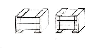
🌲Due to the high rated voltage, sufficient insulation spacing is required between the two plates, so plate-type high-power ceramic capacitors usually need to make their insulating edges into crimping flanges. As shown on the left in Figure 3.82.
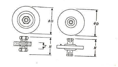
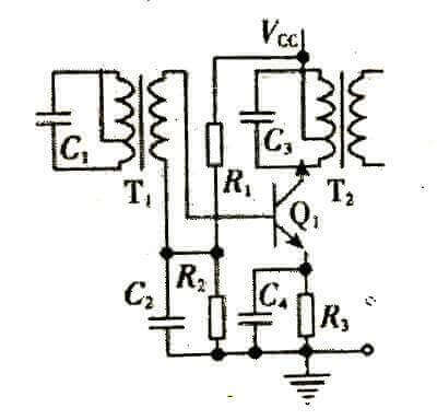
🌳If the current is large, the lead-out electrode is either connected to the external electrical connection with bolts, or is drawn from the copper plate electrode. Generally, the reactive power of high-frequency power ceramic capacitors is very large, and good cooling is required. Since high-frequency power ceramic capacitors work in a resonant tank circuit, the resonant frequency is extremely sensitive to changes in capacitance. Generally, the dielectric of this type of ceramic capacitor is the first type of ceramic dielectric, which has very good temperature stability. Applications of Ceramic Capacitors:Even as a power supply bypass for a high-frequency power circuit, it needs to flow a high-frequency alternating current generated by a high-frequency power circuit, that is to say, the high-frequency power bypass capacitor actually works in a high-frequency state, requiring A medium with low dielectric loss, so it is basically the same as that of a capacitor in a resonant tank circuit. Different from the general low-frequency circuit, the gain of the high-frequency power amplifier circuit is represented by the power gain. Therefore, the coupling capacitor will also flow a significant current, but it is smaller than the final stage current. General data for high frequency ceramic capacitors are shown in Table 3.20 and Table 3.21. See Figure 3.3 for the shape of other high frequency power ceramic capacitors.
3.20Applications-of-Ceramic-Capacitors.jpg)
3.20Applications-of-Ceramic-Capacitors.jpg)
3 Applications of ceramic capacitors in timing circuits, oscillators, clock circuits, delay circuits, and filters
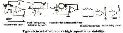
🌴In addition to bypass filtering applications, ceramic capacitors can also be used in circuits such as oscillation, timing, clock, delay, and filters. In the application of these circuits, capacitors should have good capacitance stability and low dissipation factor. In this way, the second type of medium cannot be used, because the temperature coefficient of the second type of medium is too large, which is extremely important.
🌱When the oscillation frequency above tens of kilohertz or the timing circuit below the ms level is required, the capacitance of the oscillation and timing capacitors is generally not large, usually below thousands of picofarads, which is the range of C0G dielectric capacitors.
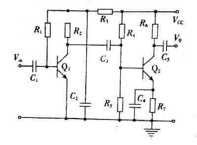
🌹Similar to film capacitors, ceramic capacitors are used in oscillator circuits, timing circuits, and delay circuits as shown in Figure 3.83.
🧶The difference is that ceramic capacitors are very suitable for applications in the RF field, such as mobile phones, set-top gold. DPS, TV regulators, etc. require capacitors with small size and good high-frequency characteristics. Because the frequency requires the lower the parasitic inductance, the better, therefore, ceramic chip capacitors become the best choice. Since the temperature coefficient of the COG medium can be close to zero, the capacitance has almost no change in the entire operating temperature range, and has no effect on the resonance frequency, timing time and delay time, and the capacitance of the capacitor is consistent. Applications of Ceramic Capacitors:Not only that, laminated ceramic capacitors can be made into very small 0402 or even 0201 package sizes.
😀Therefore, it can also be used in general circuits, such as multivibrators, integrator circuits, and timing circuits, as shown in Figure 3.84.
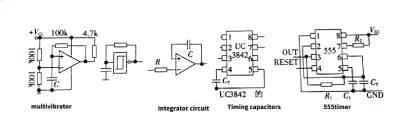
🦔The oscillation frequency of the multivibrator on the right side of Figure 3.84 is 100 kHz, and only 75 pF is required for the timing capacitor. Applications of Ceramic Capacitors:If the comparator in the circuit is packaged with SO8, and the resistor and capacitor are both packaged in 0805, the area of the circuit board will be greatly reduced; In the high-speed integrating circuit, the capacitance range of the integrating capacitor is about tens of picofarads to hundreds of picofarads, and C0G dielectric capacitors can be selected. In the module power supply, engineers often like to use UC3842/3 as the control chip, and its timing capacitor is about 470~3300pF, and the 0805 or even smaller packaged COG dielectric ceramic capacitor can be used. The timing capacitor of 555 timer can also choose COG dielectric ceramic capacitor.
🐾It should be noted that the second type of ceramic dielectric capacitors must not be used in the above applications (the capacitance of which changes too much with the temperature of the appliance). The author once used the second type of ceramic capacitors as oscillating capacitors. , but as the temperature of the capacitor increases, the oscillation frequency increases significantly, far exceeding the performance requirements.
🐉There are many application circuits for ceramic capacitors, such as high-frequency coupling, high-frequency bypassing, etc.