🌻An electrolytic capacitor differs significantly from other types in that its dielectric is an extremely thin anodic oxide film electrolytically generated on the valve metal, the thickness of which is closely related to the applied voltage. The oxide film is the heart part of the electrolytic capacitor, and its quality is related to the product performance, so it is very important. This chapter introduces the basic electrolytic capacitor anodic oxide film growth technology, that is, the enabling (forming) technology, which is generally called the forming technology in the industry, or “chemical formation” in Japanese.
1 Basic knowledge of aluminum foil empowerment
1.1 Enabling kinetics of anodized films
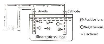
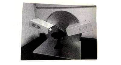
🌞Electrolytic capacitor anodic oxide film growth technology.The energization of the anodic oxide film is carried out in the electrolytic cell. The principle is shown in Figure 4-1. The valve metal is the anode, and the oxide film is gradually energized on it, so it is called anodic oxidation. The voltage applied on both sides of the oxide film is equal to the applied voltage minus the voltage drop caused by the internal resistance of the electrolyte and the polarization voltage generated by the anodization process.
🌝Anodizing energization starts with a very thin oxide film, which can be rapidly thickened by applying a voltage of just a few volts. Then, as the thickness of the oxide film increases, it becomes difficult to thicken it, so in order to keep the thickness of the oxide film increasing at a constant rate, the applied voltage needs to be continuously increased. Every time the thickness of the oxide film increases △x, the voltage △U needs to be increased. Generally, under the conditions of constant energizing current density and constant temperature, the value of △U/△x does not change with the increase of the film, and this stable value is the steady-state field strength when the oxide film is energized. Different types of valve metals have different values. Figure 4-2 shows the relationship between steady-state current density and steady-state field strength when common valve metals energize the oxide film.
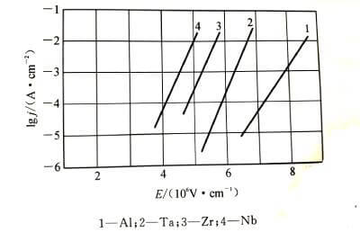
The relationship between current density and field strength conforms to formula (4-1):


⭐️According to solid-state physics to deduce the potential barrier model of ionic conduction in ionic crystals, the basic equation of oxide film growth, Mott-Cabrera conductance equation, can be analyzed. 4-3 are schematic diagrams of the potential barrier model of the growth process of the anodic oxide film.
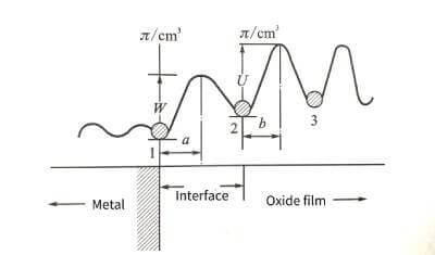
🌟When the oxide film layer is very thin in the initial stage of energization, the resistance of metal ions to migrate into the film mainly exists at the interface of the metal oxide film. ionic compound. Therefore, assuming that the metal ion is at the interface position “1” between the metal and the oxide wax, it must overcome the interface barrier W to jump into the stable position “2” in the oxide film. The interfacial barrier is sometimes also referred to as the activation energy of the metal ion escaping from the lattice into the interstitial site of the oxide film. Due to the presence of the applied electric field, the interface barrier is reduced to
![]()
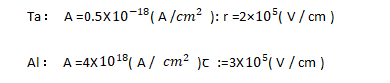
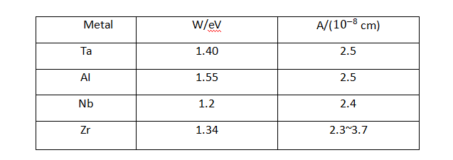
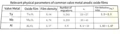
✨In the formula: q is the charge of the metal ion; E is the field strength in the film; a is half the width of the interface barrier. The data for the a and W values of common valve metals are listed in Table 4-1.
⚡️The probability that each metal ion can jump over the potential barrier and jump into the oxide film along the electric field direction per unit time is:

💥In the formula: Boltzmann constant: T is the absolute temperature: v is the frequency of thermal vibration of metal ions in the lattice. If there are n metal ions per unit surface area on the interface ready to jump over the interface barrier, the ionic current density is
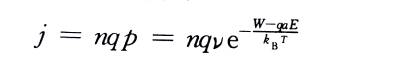
In the formula: q is the charge carried by each metal ion.
🔥Metal ions also have the probability of rebounding against the direction of the electric field, but when the field strength in the film is very high, the probability of the rebounding process is very small and can be ignored, which can be considered to be determined by the ion current density in the direction of the electric field.
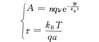
Comparing formula (4-6) with formula (4-1), we can get
🌈When the film is thick, for example, more than 100 nm, the metal ions will collide with the ions that make up the oxide film structure and stay in the film during the process of passing through the film, and finally exist in the form of interstitial ions. Therefore, the number of metal ions that jump over the interface barrier is greater than the number of ions that can finally energize the newly formed oxide film, resulting in a certain interstitial ion concentration N in the film, and the concentration varies with the distance of the interstitial ions from the interface. Change. Electrolytic capacitor anodic oxide film growth technology.Due to the existence of these space charges, the additional field strength in the oxide film is no longer a constant value E, but a variable affected by the ion concentration. Interstitial ions have to overcome a potential barrier U that is larger than the interface barrier W when they migrate in the oxide film. So the ionic current density is:
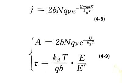
☀️It can be seen from formula (4-9) that if E is independent of temperature, then ꞇ is proportional to temperature. However, experiments show that in the range of 0~80℃, the ꞇ value of aluminum oxide film has little relationship with temperature, and the same is true for niobium oxide film in the range of 20~60℃. This is because E, which includes space charge effects, is also temperature-dependent.
⛅️The above analysis shows that the interface barrier between the metal and the oxide film only plays a leading role in the control of the oxide film growth, and the final energization speed of the oxide film mainly depends on the state of the oxide film itself.
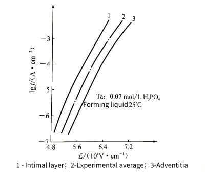
❄️At high field strength, the relationship between Igj and E appears nonlinear. This phenomenon is shown in Figure 4-4. Therefore, formula (4-1) needs to be modified as follows to make it more in line with the actual situation.

☃️In the formula: j0, U, a, B and other constants are related to the properties of the anodic oxide film of a certain metal.
1.2 The enabling voltage limit and flash voltage of the anodized film
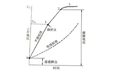
⛄️When the voltage is continuously increased while the energizing current density remains unchanged, the curve shown in Figure 4-5 can be obtained. In the electrolytic cell, with the increase of the energizing voltage, the thickness of the anodic oxide film will increase (0-1). If you continue to boost the voltage under the premise of keeping the current density unchanged, the energization speed will be slower.
🌊The drop is accompanied by an intensifying flash-fire phenomenon occurring on the anode, accompanied by the bubbling of oxygen. Electrolytic capacitor anodic oxide film growth technology.The flash fire is because the oxygen ion concentration increases to the potential where electrons can be released, and the free electrons are accelerated into the film under the action of the electric field, hit the oxide film structure, and develop into local electrical breakdown.
🍏On the other hand, the more bubbles that emerge, the larger the proportion of oxygen ions supplied by the electrolyte that fail to combine with metal ions, the lower the energizing efficiency, and the lower the energizing speed. When a certain voltage is reached (“2” in the figure), the spark intensity increases, and a “crack” sound can be heard during the flash fire. At this time, the voltage cannot continue to increase, and the energization is terminated. The voltage at this time is called the limit The forming voltage, also known as the breakdown voltage. The forming voltage cannot exceed this value.
☔️The valve metal oxide film flash voltage (U flash) has the following main factors:
(1) The properties of the valve metal itself.
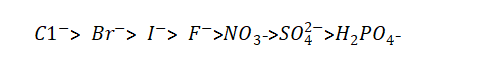
(2) The composition of the energizing liquid. Electrolytic capacitor anodic oxide film growth technology.When chlorine, bromine, iodine and other non-oxygen anions exist in the electrolyte, because of their strong activation ability and lower potential than oxygen ions, they have a strong ability to release electrons, which reduces the flash voltage. And can also destroy the oxide film. The order of ions that deteriorate the dielectric properties is
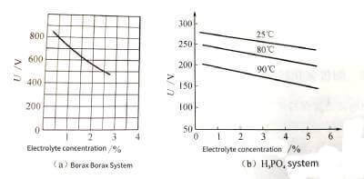
(3) The concentration of the enabling solution. Within a certain concentration range, the more concentrated the electrolyte, the lower the resistivity. Since the higher the resistivity is, the higher the flash voltage is, so the electrolyte with a higher concentration generally has a higher flash voltage. As shown in Figure 4-6.
🍐It should be noted that the flash voltage value is independent of the surface morphology of the foil. The clear foil has the same flashover voltage as the etched deep hole etched foil.
1.3 Thickness measurement of energized oxide layer
🍊Because the oxidation itself is very thin, only tens of nanometers or hundreds of nanometers in thickness, and it is in close contact with the valve metal, and the general valve metal surface is intentionally corroded to cause microscopic unevenness, so it is not feasible to directly mechanically peel off and measure the thickness. There are roughly four kinds of thickness measurement methods that can be used in actual operation: electricity method, weighing method, capacitance measurement method and ellipsometry method. These methods need to know some quantity constants of the anodic oxide film in advance, such as dielectric constant, refractive index, and even the refractive index of the valve metal itself, as well as the molecular formula and molecular weight of the oxide film, in addition to the current efficiency of the film energization process and the amount of oxygen released circumstances must also be considered.
1.3.1 Electricity method
🍋According to Faraday’s law of electrolysis, the volume of oxides produced at a constant current density is proportional to the total charge. Electrolytic capacitor anodic oxide film growth technology.If the electrode surface area A is known, its thickness d is

🍌In the formula: Q is the total amount of electricity; M is the molecular weight of the oxide; n is the current efficiency (if there is no oxygen release, it can be assumed to be 100%); z is the valence of the metal oxide; F is the Faraday constant: p is the oxide’s density. The measurement accuracy of this method depends to a large extent on the accuracy of p and A.
1.3.2 Weighing method
🍉Measure the quality of the electrode before and after energization (used to be called “weight” in engineering), and the incremental part is the quality of the oxide film. If the oxide composition and density are known, it can be calculated as follows
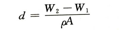
🍇In the formula, w 1 and W 2 are the weight of the anode electrode before and after energization, respectively; A is the surface area of the electrode; p is the density of the oxide. Its measurement accuracy depends on the measurement accuracy of the weight.
1.3.3 Capacitance method
The energized AC capacity can be accurately measured. If the relative permittivity and electrode area of the oxide film are known, its thickness can be calculated as follows:
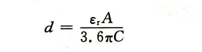
🍓In the formula: , is the relative dielectric constant of the oxide film: A is the area of the double-sided electrode: C is the measured capacitance.
1.3.4 Ellipsometry
🍈Using the polarization effect of light, high-precision thickness data can be obtained. Electrolytic capacitor anodic oxide film growth technology.But the object to be tested must be a foil sample with a very high surface finish. Neither corroded foils nor porous blocks can be measured with this method. The measurement principle is shown in Figure 4-7.
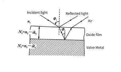
🍒The single-wavelength laser beam is converted into elliptically polarized light after passing through a polarizer and a 1/4 wavelength plate, and then shot to the surface of the sample at a certain angle. After reflection, the polarization state of the light changes.Electrolytic capacitor anodic oxide film growth technology. By measuring its relative amplitude attenuation tanψ and retardation Δ, the refractive index and thickness of the oxide film can be obtained indirectly through computer software calculation.
1.4 Product of forming voltage and capacitance of oxide film
🍑When the effective surface area of the valve metal anode remains unchanged, under the same energizing conditions (such as electrolyte and temperature), the energizing voltage is generally proportional to the thickness of the oxide film, that is
🥭In the formula: a is called the energization constant, which is related to the valve metal material, the energizing electrolyte and the temperature.
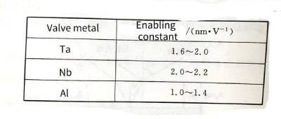
🍍The energizing constants of various valve metal materials are shown in Table 4-3.

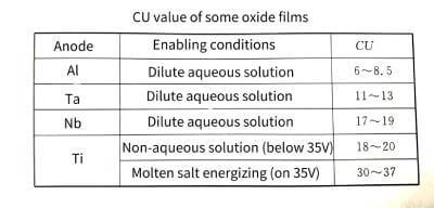
🥝When the energizing electrolyte is selected and the temperature is constant, no matter what current density boost is used (within a reasonable range), the structure of the energized oxide film is basically unchanged, that is, it is constant. Therefore, when the valve metal anode material and its effective surface area are unchanged, the product of capacitance and energization voltage (CU value) for different capacitances is a constant. This conclusion has an important guiding role for the selection of aluminum foils with different corrosion hole sizes for energization.
🍅In order to ensure that the capacitor can work reliably, the general enabling voltage is proportional to the working voltage (or rated voltage U ,). The proportional coefficient of aluminum is generally between 1.3 and 1.5, and the proportional coefficient of tantalum is between 3 and 5. Under the condition that the ratio of the energizing voltage to the working voltage of the electrolytic capacitor remains unchanged, there are
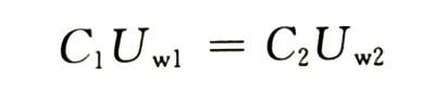
That is, the product of capacitance and working voltage (rated voltage) is also a fixed value.
🍆The CU value can be used to compare the enabling performance of different valve metal materials. From the CU values of valve metal oxide films in Table 4-4, it can be seen that under certain energizing conditions, the product of different valve metals is quite different. This data can be used as an important reference for the development of new anode materials.
🥑In actual situations, different corrosion processes and even different corrosion production lines are not completely fixed values, and the most appropriate energizing voltage should be selected according to the actual situation.
1.5 The relationship between the structure of the energizing oxide film and the energizing solution
🥦Alumina often exists in three crystal forms. After high temperature treatment, alumina is a-type, which belongs to orthorhombic system, and the crystal structure is the most compact; at lower temperature, Y-type can be obtained, which is a cubic crystal system with spinel structure. , the density is slightly lower than that of type a, and it can also be converted to type a at high temperature: there is also β type, which belongs to the hexagonal crystal system, with the lowest density and the worst hardness, in which a small amount of other alkaline oxides (such as ,0 and O). In addition, according to the X-ray diffraction refinement analysis, it is found that there are ɧ- (equiaxed crystal system), p- (crystal system uncertain) X- (hexagonal crystal system), δ- (tetragonal crystal system) θ- (monoclinic crystal system) ) are equivalent.
🥬The aluminum anodic oxide film is energized in different types of electrolytes, and the oxide film layers with different structures will be obtained. According to the electrolysis results of aluminum in it, the electrolyte can be divided into three categories: the first category is the electrolyte that neither dissolves aluminum nor dissolves the oxide film, generally it is an oxyanion weak acid or weak acid ammonium salt, such as boric acid (ammonium), Adipic acid (ammonium), citric acid (ammonium); the second type is the electrolyte that can both dissolve the oxide film and generate the oxide film, generally an oxyanion strong acid or medium strong acid, such as sulfuric acid, phosphoric acid, oxalic acid; the third The type is an electrolyte that does not grow an oxide film and dissolves aluminum, generally an anionic acid or salt that does not contain oxygen, such as hydrochloric acid, halide. Because energization requires the growth of an oxide layer, the energization process does not use a third type of electrolyte. The first type of electrolyte can energize the oxide film with a dense structure, and the second type of electrolyte can obtain an oxide film with a porous structure.
1.5.1 The first type of electrolyte that dissolves neither aluminum nor oxide film
🥒The first type of electrolyte that does not dissolve aluminum and aluminum oxide film, the most common are boric acid and borate aqueous solution, as well as adipic acid and adipic acid salt aqueous solution, azelaic acid and azelaic acid salt aqueous solution used in recent years, in addition It is an organic acid with a hydroxycarboxylic acid HO-0 COOH group and its salt aqueous solution, such as citric acid, tartaric acid, and salicylic acid.
🥕If energized at room temperature or above, an amorphous film will be obtained, whose structure is mainly amorphous and contains very small amounts of aluminum oxide, crystallites and aluminum hydroxide, which is different from natural The structure of the oxide film is similar. If it continues to be heated to about 100 °C, the energized amorphous film will be transformed into a structure type dominated by aluminum oxide crystalline phase.
🧅If it is energized at a temperature of about 95 C, it can directly generate a dense oxide film structure mainly composed of Al2O3 crystal, which is suitable for the working medium of electrolytic capacitors. In the manufacturing process, sometimes after energization and drying of moisture, high temperature heat treatment at about 400~500 ℃ is carried out to completely convert the film structure into a crystalline type to meet the needs of high working voltage capacitors. For low-voltage capacitors, considering that the oxide film may be thickened due to heat treatment, the capacitance may decrease, and some do not undergo high-temperature baking, but the capacity stability will be improved after such high-temperature treatment.
🥔Sometimes the energized aluminum oxide film is not sufficiently resistant to hydration, and the aluminum oxide may dissolve and form an aluminum hydroxide layer. It has the properties of a porous film, which can make the insulating properties of the oxide film lose. Correspondingly, the capacitor will gradually lose its capacitance and the leakage current will also increase sharply. The general solution is to perform high temperature heat treatment after the membrane is energized to convert the abdominal layer into an aluminum oxide membrane. In addition, a small amount of phosphates can also be added to the energizing solution or immersed in a phosphate solution after energization. Since aluminum ions in the oxide film react with phosphate radicals to form aluminum phosphate, oxygen-containing substances (such as water) can be hindered. The migration of the oxide film inside, so that the porous aluminum hydroxide cannot be generated, significantly improves the hydration resistance and moisture resistance of the oxide film. In addition to phosphates, commonly used anti-hydration inhibitors include silicates, arsenates, periodates and tungstates, etc., but generally lower-cost phosphates are used in the production of aluminum electrolytic capacitors.
1.5.2 The second type of electrolyte that can both dissolve and grow oxide films
🍠In some electrolytes such as oxalic acid, sulfuric acid, and phosphoric acid, two opposite reactions of dissolving the oxide film and energizing the oxide film occur simultaneously, that is,
(1) Anodizing process of aluminum:
![]()
(2) The process of aluminum oxide being dissolved:

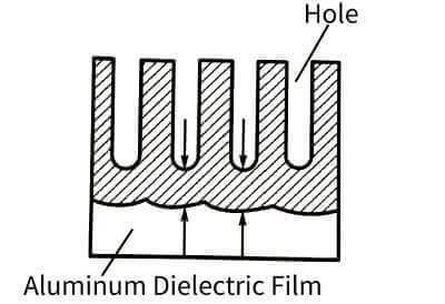
🥐At the beginning, a dense aluminum oxide film will be formed on the surface of aluminum, but due to the dissolution of the electrolyte, many parts of the surface of this dense film begin to corrode, and the current is concentrated here to try to repair these local damages, which makes the electrolyte nearby. The temperature is higher than the general part, but it makes the dissolution
Acceleration, the result is many small holes. As shown in Figure 4-9.
🥯The electrolyte can continue to contact the aluminum through the holes and continue to energize the oxide film. In this way, the oxide film grows on one side and is etched on the other side, and the final thickness of the film is determined by the balance relationship between these two processes. The energized oxide film through this process is full of honeycomb-like pores. Its structure is roughly like many hexagonal prisms (single cells), each single cell consists of a central hole and pore walls and dense The bottom of the hole is formed, as shown in Figure 4-10.
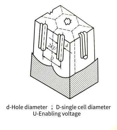
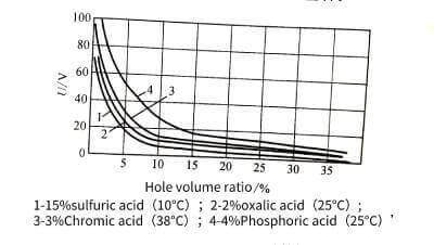
🍞The size of a single cell is related to the type of electrolyte, energizing voltage and temperature, but has little to do with the length of energizing time. The size of the single cell has a linear relationship with the energizing voltage. When the voltage increases, the size of the single cell increases, and the number of holes decreases accordingly. The volume occupied by the holes and its energizing voltage have the relationship in Figure 4-11. Raising significantly reduces the pore volume. In addition, the pore volume also increases with the increase of temperature, decreases with the increase of current density, and is related to the type of electrolyte and its concentration. When energized in oxalic acid or chromic acid and phosphoric acid, the number of pores is much less than that in sulfuric acid, but the diameter of the pores is larger. The diameter of the hole is mainly determined by the type and temperature of the electrolyte, and has nothing to do with the magnitude of the energizing voltage. For example, it is about 6~12 nm in sulfuric acid, but it can reach about 30 nm in other acids.
🥖Since a lot of heat is released during the energizing process of the porous film, the pore wall tends to locally form a hydrated oxide film. Partially hydrated porous membranes with a “crystal green” structure, the thickness of which can even reach the micron level, but still retains a very thin dense membrane under the porous membrane. In the manufacture of electrolytic capacitors, this step is called “pre-energization”. Electrolytic capacitor anodic oxide film growth technology.On this basis, the next step is continued to generate a dense oxide film corresponding to the energizing voltage value. This process is commonly known as “enabling”.
🌭The pre-energized porous film can protect the dense film generated by the subsequent energization process from mechanical damage, and isolate the working medium from direct contact with external operating objects; it can absorb the working electrolyte and help to repair the dielectric film; It can reduce the dissolution of the dense film in the working electrolyte
🍔Therefore, the service life of the capacitor is extended and the growth rate of the leakage current is reduced; it can also shorten the energization time and reduce the power consumption, and shorten the aging time to a certain extent. Then adding this process also increases the production cost. On the other hand, if the thickness of the porous film layer is too large, the anode surface area and the corrosion coefficient value will be greatly reduced, so that the capacitance will drop significantly. Therefore, low-voltage capacitors do not use a pre-energizing process, and general high-voltage capacitors are rarely used. An exception is high-voltage bulk electrolytic capacitors for energy storage. The country guarantees reliability because it needs to withstand the electric shock of hundreds of thousands of repeated charging and discharging.
🥪It is worth mentioning that the porous film aluminum foil obtained by pre-energizing in oxalic acid or sulfuric acid, if treated with boiling water, the porous film will be transformed into a larger diaspore film: it will make countless small particles on the film. The holes are filled and become a sealing oxide film.
🍭The study found that if the hydrated sealing film continues to be energized in the first type of electrolyte, the obtained composite film has better performance than the pure oxide film, and can operate in a wide temperature range (-100~+150℃) It maintains quite good capacitance address stability, and the insulation quality is better than that of paper capacitors. In addition, compared with the dense film, the oxide layer of the gift film can grow thicker, so this station capacitor can work at a higher voltage (hundreds of volts), and it also has a self-healing effect. However, the purity requirements of raw materials and water in this process are very strict, so the cost issue needs to be weighed.
1.6 Corrosion of hydrated oxide film on the surface of aluminum foil
🍿A hydrated oxide film can be formed by the action of metal aluminum and moisture. After the uncorroded aluminum foil is annealed, the surface will accelerate the formation of this oxide, and the corroded aluminum foil will also form this hydrated oxide film in deionized water.
1.6.1 The structure of the hydrated oxide film
🍩The structure of the hydrated oxide is closely related to the water temperature: if the water temperature is lower than 75 °C, a film mainly composed of (water alum) or amorphous aluminum hydroxide will be formed, and its insulation performance is not good; if the water temperature is higher than 75 °C Above ℃, a thin layer mainly composed of (water and aluminum in or in the form of AI100H) and other reaction products will be formed. With the increase of the water temperature and the prolongation of the reaction time, the thickness of the hydrated oxide film and the percentage of the diaspore content will increase. between 300mm. The higher the temperature, the more diaspore content and the less content. If the film prepared in 155 ℃ water vapor, its diaspore content is the most.
🍪Because diaspore is a relatively insoluble oxide film, it can provide corrosion protection to aluminum foil before and after energization, and can shorten the energization time and improve the performance of capacitors.
1.6.2 Influence of impurities
🌰A small amount of impurities in deionized water can have a great impact on the performance of the hydrated oxide film. The general impurities are mainly chloride ions and silicon dioxide, containing more than 2 ppm (2X, 2 parts per million), the film energized in the water, the performance of the capacitor will be unstable, and the gas ions will affect the performance of the hydrated oxide film. impact is more pronounced. Therefore, in order to ensure that the pH value of deionized water is between 5 and 6, it is generally adjusted by adding airless phosphates to make the hydration film grow well.
1.6.3 Effects on medium and high voltage foils
🥜For high-voltage and medium-voltage (above 160 V) capacitors, if a thick hydrated film has been formed on the etched aluminum foil before energization, the dielectric film will grow under the hydrated film during energization, and part of it will grow. The hydrated membrane is converted into a dense membrane, which not only reduces the current dissipation during energization energy consumption, improve the energization efficiency, and the energized composite film is higher than the pure dense film in terms of electrical strength. In order to achieve this effect, the formation of the hydration membrane should be as close as possible to the energizing process, otherwise the hydration membrane will gradually “age” after a long time, and it is difficult to completely transform into a dense film in which some water molecules or hydroxides remain. They absorb energy under an AC electric field (DC superimposed AC), increasing the capacitor losses. With the hydrated membrane, the energization of the high-voltage anode foil does not need to be pre-energized, and there is no effect on the corrosion coefficient.
1.6.4 Effect on low voltage foil
🥎The presence of a hydrated membrane is disadvantageous for low-voltage anode foils. Since it is naturally generated in the process and in a humid environment, even after etching and cleaning, the thickness is generally greater than 10 nm, and this thickness can reduce the voltage by about 2V (1~1.4 nm/V). This makes it very difficult to fabricate large-capacity anode foils with extremely low operating voltages (below 3V for enabling voltages).
1.6.5 Influence on the negative electrode foil
🎾When the negative electrode foil is stored in humid air, a hydrated film of about 10-30nm will be formed, and this part of the hydrated film layer will lead to a significant decrease in the negative electrode capacitance.Electrolytic capacitor anodic oxide film growth technology. In capacitors, the effective capacitance of low-voltage capacitors is greatly reduced due to the series relationship between the negative electrode capacitance and the anodic oxide film capacitance. Overdose must be prevented.
1.7 Electrolytic capacitor anodic oxide film growth technology:Rectification effect of anodized film
🌋The anodic oxide film energized on the valve metal has unidirectional conductivity. When the anode metal is connected to the “ten” of the power supply voltage (the negative electrode of the capacitor is connected to the “one” pole of the power supply), the current value is very small, correspondingly, the insulation resistance of the oxide film can be considered to be large; but when the one “pole of the power supply voltage is connected to the “one” pole of the power supply After the anode metal, the current is very large, the capacitor continues to heat up, and eventually fails due to damage. At this time, it can be considered that the insulation resistance of the oxide film is very small. This is the conductance asymmetry of the oxide film, also known as “unidirectional conductivity” “”rectification effect” “has polarity and so on.
There are two main theoretical explanations for the rectification effect.
1. The theory of p-n junction of anodic oxide film
💰The p-n junction concept of semiconductors can be applied to the anodic oxide film.Electrolytic capacitor anodic oxide film growth technology. Both P-n exist at the interface between the oxide film and the electrolyte. The entire anodic oxide film is an n-type semiconductor, and excess metal atoms are distributed asymmetrically in the film. Near the outer surface of the film, the composition of the film conforms to the stoichiometric ratio of the oxide film.
⏳When the base metal is connected to the positive electrode of the power supply, the electrolyte provides a very thin oxygen ion layer (ie, an electric double layer composed of anions) at the oxide film/electrolyte interface, which can be considered as a P-type semiconductor with hole conductivity. A P-n junction is formed. The electrons in the n-type region and the holes in the p-type region will diffuse to each other, so that the thin layer lacking electrons in the n-type region is positively charged, and the thin layer lacking holes in the p-type region is negatively charged, and a thin layer is generated between the two thin layers. The electric field forms a blocking layer to prevent the continued diffusion of electrons and holes, as shown in Figure 4-12.
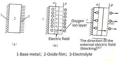
📡When the direction of the applied electric field is the same as that of the electric field of the barrier layer (that is, the base metal is connected to the positive), the barrier of the barrier layer is raised, resulting in the blocking effect.
If the power supply is reversed, the adsorption of the oxygen ion layer at the membrane/electrolyte interface is destroyed, and the p-n junction disappears.
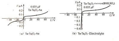
❣️In addition, studies have shown that the rectification effect of the electrolyte-free anodic oxide film is not obvious at room temperature and low voltage; while the overall flow effect is very prominent when the electrolyte is used as the counter electrode.Electrolytic capacitor anodic oxide film growth technology. Figure 4-13 shows the difference in I-U characteristic curves caused by these two different counter electrodes. Therefore, the oxide film/electrolyte interface plays an important role here.
2. Defect theory of anodized film
❤️The oxide film itself must have defects such as defects, voids, and fine cracks, through which current can flow. In the case where the positive electrode of the power supply is connected to the base metal, the pores or cracks are blocked by the oxygen provided by the electrolyte, thus blocking the passage of current, forming a blockage, and showing a large resistance. and
When the connection is reversed, hydrogen ions will accumulate in the pores and other defects. Because of its small size, it can pass through the cracks and pores. When the electrons supplied by the power supply reach the hydrogen release potential, they will become hydrogen bubbles, which are accompanied by the precipitation of hydrogen ions. The electron current is shown as a small resistance externally.
1.8 Self-healing effect of anodic oxide film
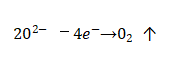
🌈During the manufacturing process and storage of the capacitor, the oxide film will be left with fine defects, cracks, nicks, voids and other defects on the surface of the oxide film due to the use of raw materials that are not pure enough and improper measures in the process. In addition, the base metal The impurity metal ions in the film act as a micro-battery for the metal ions in the film layer, and also cause some local areas of the oxide film to be damaged. At this time, if the working voltage is applied to the capacitor immediately, the film in the weak area will be broken down. However, if the applied voltage is gradually increased (this is especially important for aluminum electrolytic capacitors that have been stored for a long time and not used), since the electrolyte there can supply oxygen ions, the damaged oxide film can quickly grow and thicken, and Patch and repair weaknesses. In the repair process, even if there are impurity ions and other defects on the surface of the film itself, so that the thickened oxide film cannot be rapidly grown there, but at the moment of the short circuit, the concentration of oxygen ions in this area suddenly increases, resulting in oxygen release, that is,
🚩Electrolytic capacitor anodic oxide film growth technology.The released oxygen bubbles will stay in the pores, like a “plug”, which isolates the direct contact between the electrolyte and the anode, and also leaves time for gradual repair of the oxide film, so as to achieve the ability to automatically restore the capacitor’s work.
♻️For electrolytic capacitors using solid electrolytes, the self-healing effect is different from that described above. When the dielectric breakdown occurs due to defects on the oxide film, the solid electrolyte manganese dioxide (p< xn--bya.cm) in contact with it will undergo chemical changes due to the local heating effect of the short circuit.
🔰It is decomposed into oxides with low oxygen content but poor conductivity, which greatly increases the resistance at the short circuit, and is electrically isolated from other areas, and the capacitor operation is not affected. As for dry capacitors of metal-oxide-film-metal system, if there is a defect on the anodic oxide film, after applying an appropriate voltage, the metal film around the defect will evaporate due to short-circuit instantaneous heat, so that the defect is isolated.