A snubber capacitor is limited by three things before capacitance ever matters: how fast its terminal voltage is allowed to change, how much peak current that implies, and how much energy it can absorb per event. On a polypropylene film part those three collapse into one line, I = C × dv/dt, and the dv/dt rating is usually the constraint that binds. Choose on capacitance and voltage alone and the part looks correct on paper and fails on the bench.
This article is the third in a series on snubber design. The first one explained where the voltage spike comes from, and the second worked out the capacitor and resistor values. What follows takes those values as given and asks a different question: can a real part survive them.
Three Ratings Decide Whether a Part Belongs in a Snubber
A datasheet for a snubber-grade film capacitor carries three numbers that matter here, and they are not interchangeable.
The first is dv/dt, the maximum rate of voltage change across the terminals, quoted in V/µs. It is written for non-sinusoidal waveforms, which is exactly what a snubber sees. The second is peak current, which for most manufacturers is not an independent measurement at all but the dv/dt figure multiplied by the nominal capacitance. The third is RMS current capability. Cornell Dubilier defines that one as the lower of two currents: the current that heats the capacitor by 15 °C, or the current that drives it to its rated AC voltage. Whichever limit arrives first governs.
Read a datasheet that quotes only the first two and you are missing the thermal half of the problem. A part can sit comfortably inside its dv/dt limit on every switching event and still run hot enough to lose life, because the events arrive tens of thousands of times a second.
Why Two Capacitors With the Same Numbers Behave Differently
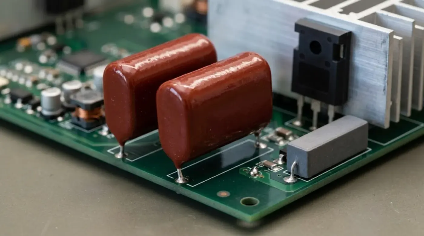
Two parts can carry identical capacitance, identical voltage rating and the same case size, and differ by a factor of fifty in what they will survive. The difference is the electrode.
A metallized film capacitor deposits a thin metal layer directly onto the dielectric. That layer is a few tens of nanometres thick, which is what makes self-healing possible and what makes the part cheap and small. It is also the current path. When a large pulse arrives, the weak point is not the polypropylene but the metal layer and the contact between that layer and the end spray.
A film/foil construction puts a separate aluminium foil in parallel with the metallized layer. The foil carries current far better, and the peak current capability rises accordingly. Cornell Dubilier’s own guidance is blunt about this: metallized film reduces peak current capability to between a third and a fifth of the equivalent high-voltage film/foil part.
| Construction | Reported dv/dt capability | Where it fits |
|---|---|---|
| Metallized film, general purpose | roughly 50 to 200 V/µs | Filtering and coupling, not snubber duty |
| Metallized polypropylene, snubber grade | about 1000 V/µs and above | Small to medium snubbers |
| Film/foil polypropylene | 2000 to 3000 V/µs | High-voltage IGBT snubbers |
| Dipped mica | above 100,000 V/µs | Small capacitance, very fast edges |
The figures above come from Cornell Dubilier’s snubber application guide and describe their own product families. Other manufacturers publish different numbers for the same categories, so treat the ratios as the useful part and look up the actual rating for the part you intend to buy. Mica is the outlier worth knowing about, because it handles dv/dt that no film part approaches, at capacitance values that stop around a few nanofarads.
The Number Your Own Sizing Produces
Here is where the ratings stop being abstract. Take the half bridge from the previous article: an 800 V bus, 40 A at turn-off, 60 nH of loop inductance, and a snubber sized at 1.5 nF, which stores 0.48 mJ at full bus voltage.
At the instant the switch opens, the snubber capacitor voltage is still near zero, so essentially the whole 40 A flows into it. The terminal voltage then rises at a rate set only by capacitance:
dv/dt = I / C = 40 A / 1.5 nF = 26,700 V/µs
Compare that against the table. A snubber-grade metallized part rated at 1000 V/µs is being asked for twenty-six times its rating. A film/foil part at 3000 V/µs is still being asked for nine times its rating. The capacitor, as sized, cannot take the event.
There are only three honest ways out, and every real design takes one of them. Split the current across several capacitors in parallel so each sees a fraction. Increase the capacitance, which lowers dv/dt in direct proportion, at the cost of board space and resistor dissipation. Or accept that the snubber is not there to swallow the whole turn-off current and size it for the energy it can actually clear, letting the switch absorb the rest inside its safe operating area.
That last option is what most commercial designs do, and it is why snubber capacitance often looks small next to the loop energy. The 1.5 nF value from the energy calculation is a starting point that the dv/dt limit then pushes upward. If a supplier quotes a snubber capacitor with no dv/dt figure at all, that is not an omission you can work around. It means the part was never specified for this duty.
Peak Current Is Not a Separate Specification
Because peak current is capacitance times dv/dt, the two cannot be traded against each other. Doubling the capacitance and halving the dv/dt rating leaves the peak current capability unchanged, and doubles the energy the part has to absorb per event. That is a worse position, not an equivalent one.
The practical use of the identity is in reading quotations. A supplier who offers a 10 nF part at 1500 V/µs is offering a peak current capability of 15 A. If your loop needs 40 A, the offer does not fit regardless of how the capacitance compares. Run the multiplication on every candidate before comparing prices, because price scales with capacitance and the part that fits is often the smaller one.
One Pulse vs a Train of Pulses
A dv/dt rating is usually quoted for a single isolated pulse, with the wording that the heat from one pulse is fully dissipated before the next arrives. That condition almost never holds in a switching converter, where the same event repeats at the switching frequency for years.
TDK handles this by publishing two parameters together rather than one. Alongside dv/dt it gives k0, the maximum permissible pulse characteristic, expressed in V²/µs. The k0 figure accounts for the shape of the waveform rather than just its peak slope, and for repeated pulses the datasheet points the reader to AC voltage against frequency curves instead of the single-pulse figure. A design that sits inside dv/dt but outside the curve for its switching frequency will still overheat.
So check the switching frequency against the AC voltage or current derating curve, not only against the single-pulse dv/dt line. That curve is where the thermal reality lives, and it is the one most often skipped.
Where the Heat Really Comes From
There are two separate heat sources in a snubber capacitor, and only one of them is obvious.
The first is the energy stored and dumped on each transition. A snubber of capacitance C charged to a voltage V stores ½CV², and that energy leaves the capacitor on the next transition. In an RC snubber the resistor is where it becomes heat, which is why the resistor sizing matters and why the snubber capacitor itself is not the part that gets hot from this mechanism.
The second is the RMS current through the capacitor’s own ESR, and this one stays in the capacitor. It scales with the square of the current and with frequency, and on a part with a modest ESR it can dominate once switching frequency rises. This is the mechanism the 15 °C temperature rise limit in a datasheet is protecting against.
Dielectric loss sits on top of both. Polypropylene is the material of choice for snubber duty largely because its dissipation factor is low, at or below 0.001 at 1 kHz on the CBB81 parts Xuansn supplies. Polyester, by contrast, has roughly fifteen times the loss of polypropylene on Cornell Dubilier’s numbers, which is why it is not used for snubbers except at low duty cycle.
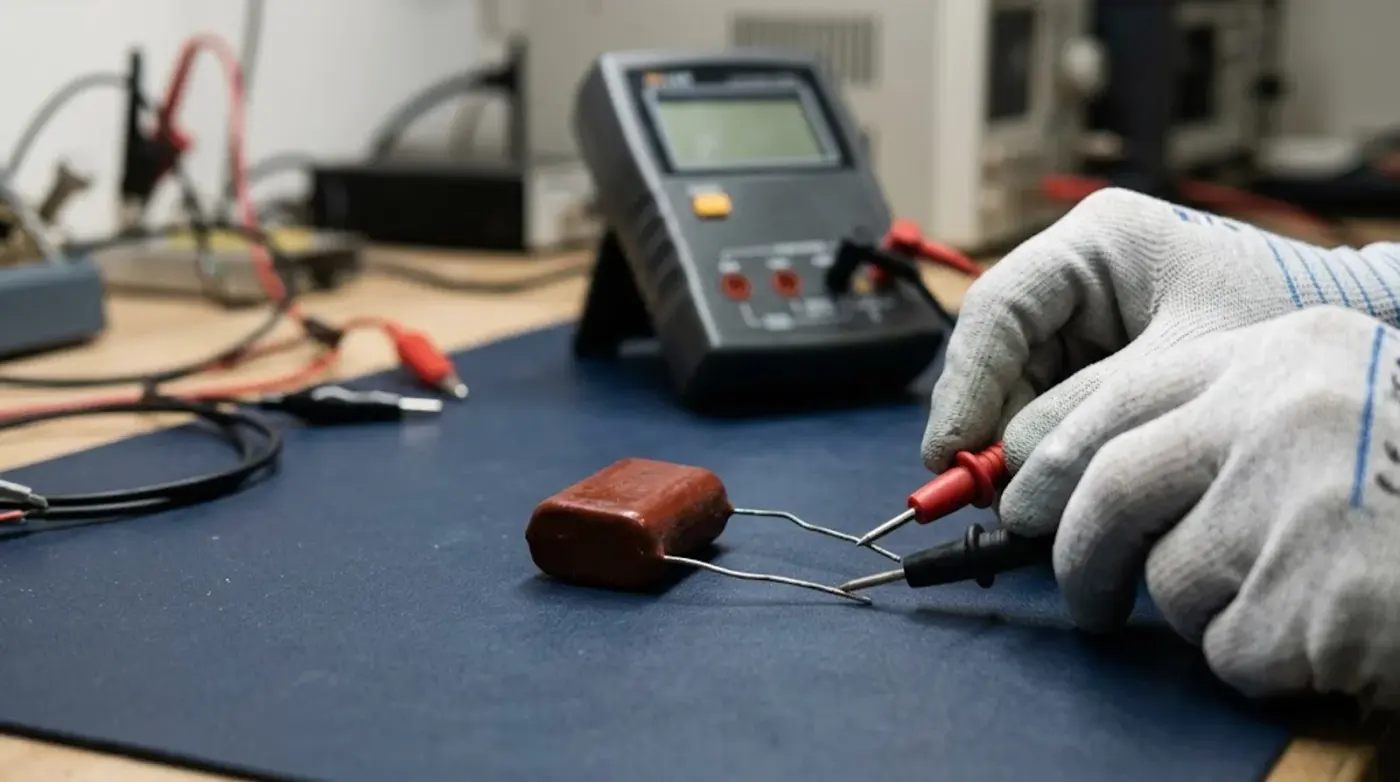
What Failure Looks Like on a Snubber Capacitor
A snubber capacitor rarely fails open or shorted without warning. The usual path is a slow loss of capacitance, and it is easy to misread.
Each self-healing event clears a small area of metallization around a dielectric defect. That is the feature working as designed, and it is why metallized film parts survive transients that would puncture a foil part. But every clearing event removes a little electrode area, and the capacitance drops. On a snubber running at high dv/dt and high repetition rate, that loss accumulates. A part that measured 1.5 nF when installed can read 1.2 nF a year later, and the snubber that was correctly sized now lets more of the spike through.
This is why a snubber capacitor should be measured on a schedule rather than only when something fails. A capacitance check against the original value, done at the same temperature and with the same meter, tells you how much margin is left. A part more than about ten percent down from its installed value is telling you the stress is higher than the design assumed.
A Short Check Before You Order
Five questions, in the order they eliminate candidates.
| Check | What to confirm |
|---|---|
| Peak dv/dt | Turn-off current divided by capacitance, against the datasheet dv/dt rating |
| Peak current | dv/dt rating times capacitance, against the current your loop actually delivers |
| Repetition | Switching frequency located on the AC voltage or current derating curve |
| Electrode type | Metallized or film/foil, and whether the rated voltage matches the bus |
| Voltage margin | Rated voltage above the peak the snubber will see, including overshoot |
Xuansn manufactures the CBB81 series for exactly this position: polypropylene dielectric with metallized film and aluminium foil electrodes in an internal series structure, epoxy encapsulated to UL94V-0, rated 2000 VDC in the 153J and 223J values, with a dissipation factor at or below 0.001. The CBB81 153J 2000 V part and the 630 VDC snubber capacitor rated for IGBT protection cover the two most common voltage classes on a bridge leg.
What Comes Next
Everything so far treats the snubber as a single capacitor across a single switch. Most real hardware does not look like that. Three-phase bridges put several snubbers in one enclosure, and the way they are mounted decides how much inductance sits in series with each one. That is where the series goes next, and it is where a correctly sized capacitor most often gets undone by the way it was connected.
Questions About Snubber Capacitor Ratings
What is a typical dv/dt rating for a snubber capacitor?
General-purpose metallized film parts run in the 50 to 200 V/µs range. Snubber-grade metallized polypropylene starts around 1000 V/µs, and film/foil constructions reach 2000 to 3000 V/µs. Dipped mica goes above 100,000 V/µs but only at capacitance values below a few nanofarads. Use the figure for the specific part rather than the category.
Can I just use a bigger capacitance to get around a dv/dt limit?
Increasing capacitance does lower the dv/dt the part sees, because dv/dt equals current divided by capacitance. It also increases the energy stored and dumped on every transition, which pushes the resistor dissipation up and can push the capacitor’s own RMS heating up with it. It is a legitimate move, but it has to be rechecked against the resistor rating and the thermal limit rather than applied on its own.
Why does my snubber capacitor lose capacitance over time?
Self-healing. Each clearing event that isolates a dielectric defect removes a small patch of metallization, and the capacitance falls slightly. This is normal and it is what makes metallized film resistant to transients. The problem is cumulative. At high dv/dt and high repetition rate the losses add up, so periodic capacitance checks are the way to know how much margin remains.
Does a higher voltage rating also raise dv/dt capability?
Usually not in the way people expect. dv/dt capability comes from the electrode structure and the contact geometry, not from the voltage rating. A higher voltage part in the same construction family often has a similar dv/dt limit while carrying less capacitance, which means a lower peak current capability. Voltage rating and pulse capability are separate axes, and a part has to satisfy both.
Have a snubber position that needs a part with a real dv/dt figure? Send the bus voltage, the turn-off current, the loop inductance you expect and the switching frequency, and Xuansn will come back with a capacitance value, a dv/dt rating and a CBB81 part number that fits. Reach us at coco@xuanxcapacitors.com, call +86-769-8166 8821, or send your specification through the contact page.