Electrolytic Capacitors – Comprehensive Technical Introduction
Electrolytic capacitors are widely used in modern electronic circuits due to their extremely high capacitance, compact structure, and cost efficiency. Compared with film and ceramic capacitors, electrolytic capacitors can achieve much larger capacitance values in a relatively small volume, which makes them indispensable in power electronics, industrial systems, communication equipment, and automotive electronics.
At the same time, electrolytic capacitors are also one of the most widely used but most failure-prone components in electronic circuits. Because of this dual nature—high performance but relatively lower reliability—they have become an “eternal research topic” in the field of electronic components.
According to electrode materials and structure characteristics, electrolytic capacitors mainly include aluminum electrolytic capacitors, tantalum electrolytic capacitors, niobium electrolytic capacitors, and polymer electrolytic capacitors. Each type has different performance characteristics and application scenarios.
1. What Are Electrolytic Capacitors?
Electrolytic capacitors are called “electrolytic” because one of their electrode systems is not a traditional metallic conductor but an electrolyte or a metal oxide layer. This structure fundamentally changes the way charge is conducted inside the capacitor.
In electrolytic capacitors, the conductive carriers are no longer electrons moving in a metal, but ions moving inside the electrolyte. This is the key distinguishing feature between electrolytic capacitors and other capacitor types such as ceramic or film capacitors.
Because of this ion-based conduction mechanism and extremely thin dielectric layer, electrolytic capacitors are able to achieve very high capacitance values, making them ideal for energy storage and power filtering applications.
2. Types of Electrolytic Capacitors
Electrolytic capacitors can be classified according to their anode materials and dielectric systems. The main types include:
- Aluminum electrolytic capacitors
- Tantalum electrolytic capacitors
- Niobium electrolytic capacitors
- Polymer electrolytic capacitors
Among them, aluminum electrolytic capacitors are the most widely used due to their low cost and large capacitance range. Tantalum and niobium capacitors are used in more demanding applications requiring higher stability and lower ESR. Polymer electrolytic capacitors represent the modern development direction with significantly improved electrical performance.
Each type plays a different role in electronic systems, depending on requirements such as ripple current capability, ESR performance, temperature stability, and size constraints.
3. Why Electrolytic Capacitors Are Widely Used
Electrolytic capacitors are the most widely used capacitors in electronic circuits because they provide an unmatched combination of high capacitance, low cost, and compact size.
They play a central role in the uses of capacitors, especially in power-related applications where large energy storage and voltage stabilization are required.
In almost every power-related electronic system, electrolytic capacitors are used for functions such as power smoothing, voltage stabilization, energy buffering, and noise filtering. These functions represent some of the most important practical uses of capacitors in modern electronics.
Without electrolytic capacitors, it would be extremely difficult to design compact and efficient power supply systems.
4. Evolution of Aluminum Electrolytic Capacitors
With the development of electronic technology, aluminum electrolytic capacitors have undergone significant evolution.
In early stages, aluminum electrolytic capacitors had large physical volume and relatively limited performance. The maximum operating temperature was often around 55°C, and they were mainly used for simple power frequency rectification and filtering applications.
Today, modern aluminum electrolytic capacitors have achieved major improvements, including:
- Miniaturization of physical size
- Reduced equivalent series resistance (ESR)
- High ripple current capability
- High temperature resistance up to 150°C
- Capacitance reaching farad-level values
- Surface-mount (SMD) structures
As a result, aluminum electrolytic capacitors are no longer limited to low-frequency rectification. They are now widely used in power electronics, high-frequency filtering, bypass circuits, and various advanced industrial applications.
5. Role of Tantalum and Polymer Electrolytic Capacitors
In applications where aluminum electrolytic capacitors cannot fully meet performance requirements, tantalum electrolytic capacitors play an important complementary role.
Tantalum capacitors are known for:
- Excellent high-frequency performance
- Low ESR characteristics
- Strong ripple current capability
- Long-term stability and reliability
Over time, tantalum capacitors have evolved from simple structures into advanced multi-anode and ultra-low ESR designs, making them suitable for high-performance electronic systems.
Polymer tantalum capacitors further reduce ESR to the lowest levels among all electrolytic capacitor types. Their solid polymer cathode structure also improves mechanical stability and makes them highly suitable for surface-mount technology.
Similarly, polymer aluminum electrolytic capacitors can reduce ESR by 1 to 2 orders of magnitude compared to traditional liquid-electrolyte capacitors, significantly improving ripple current handling and extending service life.
6. Why Large Capacitance Is Required in Circuits
One of the most important applications of capacitors is to smooth pulsating DC voltage into stable DC output during rectification.
For example, in industrial power conversion systems, AC voltage is first rectified into pulsating DC. This pulsating waveform must be smoothed using capacitors to provide stable DC power for electronic circuits.
Taking a single-phase bridge rectifier as an example:
- Each rectifier diode conducts only for a few milliseconds (typically around 3 ms)
- During the remaining time, the capacitor supplies energy to the load
- This causes the capacitor voltage to fluctuate significantly during each cycle
As a result, large capacitance is required to reduce voltage ripple and maintain stable output. In many cases, the required capacitance value is too large for film or ceramic capacitors to achieve economically.
7. Why Electrolytic Capacitors Were Developed
The development of electrolytic capacitors was driven by the need for large capacitance, small volume, and low cost.
One key approach is increasing electrode surface area. This is achieved by:
- Roughening the surface of aluminum foil
- Chemical etching to create porous structures
- Increasing effective surface area by hundreds of times
However, this introduces a critical challenge: the dielectric layer must be extremely thin and uniform while conforming perfectly to a highly rough surface.
Conventional film and ceramic capacitors cannot meet these requirements. This is why electrolytic capacitors were developed as a practical solution to this engineering problem.
8. Formation of Dielectric Film in Electrolytic Capacitors
The dielectric layer in electrolytic capacitors is formed through an electrochemical process called anodization.
In aluminum electrolytic capacitors, aluminum is oxidized to form a dense aluminum oxide (Al₂O₃) layer. This oxide layer acts as the dielectric material.
Key characteristics include:
- Dielectric thickness is precisely controlled by voltage
- Approximately 1.2–1.5 nm of oxide is formed per volt
- High dielectric strength (~80 V/μm)
- Stable insulation properties
Other valve metals such as tantalum, niobium, and titanium can also form stable oxide dielectric layers, which are widely used in different types of electrolytic capacitors.
9. Electrode Structure and Surface Area of Electrolytic Capacitors
To achieve extremely high capacitance, electrolytic capacitors rely heavily on electrode surface engineering.
The anode foil (especially aluminum foil) is chemically etched to create a highly rough and porous structure. This increases the effective surface area by hundreds of times compared to its geometric surface.
On the cathode side, a conductive electrolyte or polymer is used to ensure close contact with the rough anode surface. This combination allows the capacitor to achieve extremely high capacitance density within a very small volume.
10. Negative Electrode Mechanism of electrolytic capacitors
Unlike conventional capacitors that use solid metal electrodes, electrolytic capacitors use a non-solid cathode system, typically in the form of liquid electrolyte or conductive polymer.
This allows extremely close contact between electrodes and significantly increases effective surface area.
However, this also introduces limitations:
- Lower conductivity compared to metals
- Higher equivalent series resistance (ESR)
- Lower temperature stability
- Reduced high-frequency performance
These trade-offs are inherent to electrolytic capacitor design.
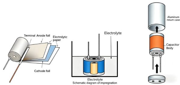
11. Structure of Aluminum Electrolytic Capacitors
A typical aluminum electrolytic capacitor consists of:
- Etched anode aluminum foil
- Aluminum oxide dielectric layer
- Separator paper
- Cathode aluminum foil
- Liquid electrolyte
- Wound cylindrical structure
These components are tightly wound into a core and sealed inside an aluminum casing to prevent electrolyte leakage and evaporation.
This wound structure allows maximum utilization of surface area while maintaining a compact form factor.
12. Manufacturing Process of Aluminum Electrolytic Capacitors
The manufacturing process of electrolytic capacitors includes several critical steps:
- Corrosion (etching): increases aluminum foil surface area
- Anodization: forms aluminum oxide dielectric layer
- Cutting: prepares foil to required dimensions
- Winding: assembles anode, cathode, and separator
- Electrolyte saturation: vacuum impregnation of electrolyte
- Sealing: prevents leakage and evaporation
- Aging (formation): applies voltage to repair dielectric defects
The aging process is especially important because it helps stabilize leakage current and repair microscopic defects formed during manufacturing.
13. Key Electrical Parameters
Electrolytic capacitors are defined by several important electrical parameters:
1.Voltage Ratings
Includes rated DC voltage, surge voltage, reverse voltage (not allowed in normal use), and transient overvoltage conditions.
2.Capacitance
Measured at 100/120 Hz under standard conditions. Typical tolerance is ±20%.
3.Leakage Current
Caused by dielectric imperfections. It decreases over time due to self-healing effects and aging.
4.Dissipation Factor (DF / tanδ)
Represents energy loss and is frequency dependent. Closely related to ESR behavior.
5.ESR (Equivalent Series Resistance)
Mainly caused by electrolyte resistance. It significantly affects efficiency, heating, and high-frequency performance.
6.Ripple Current
AC ripple current causes internal heating. It is one of the main factors determining capacitor lifetime.
14. Operating Temperature and Lifetime
The operating temperature range of electrolytic capacitors is mainly determined by the electrolyte properties.
At high temperatures, electrolyte evaporation accelerates, reducing capacitance and increasing ESR. At low temperatures, the electrolyte becomes viscous, reducing performance.
Typical temperature ratings include:
- 85°C for general applications
- 105°C for industrial applications
- 125°C to 150°C for high-temperature environments
Lifetime is directly related to temperature and typically ranges from 1000 hours to over 10000 hours depending on design.
15. Equivalent Series Resistance (ESR)
ESR is one of the most critical parameters of electrolytic capacitors.
It mainly comes from electrolyte resistance and internal structural losses. Compared with ceramic and film capacitors, electrolytic capacitors generally have much higher ESR values.
For example:
- Small capacitors may have ESR around tens of ohms
- Larger capacitors reduce ESR but still remain relatively high
High ESR leads to:
- Heat generation
- Reduced ripple current capability
- Lower high-frequency performance
This is why low-ESR and polymer electrolytic capacitors have become an important development direction.
16. Ripple Current Capability
Ripple current capability is one of the most important performance parameters of electrolytic capacitors, especially in power electronics and switching power supply applications.
When alternating ripple current flows through the capacitor, internal resistance (ESR) causes power loss in the form of heat. This self-heating effect directly influences the internal temperature of the capacitor and has a major impact on its lifetime and reliability.
If the ripple current exceeds the rated specification, the internal temperature will rise rapidly, accelerating electrolyte degradation, increasing ESR over time, and significantly shortening the operational lifetime of the capacitor.
Therefore, ripple current rating is a critical design parameter in power supply systems, inverter circuits, motor drives, and renewable energy applications where continuous high-current operation is required.
17. Conclusion
Electrolytic capacitors are fundamental components in modern electronics due to their unmatched capacitance density and cost advantage.
Although they have inherent limitations such as ESR, leakage current, and finite lifetime, continuous technological improvements—especially in polymer electrolytes and advanced electrode design—are significantly improving their performance.
Today, electrolytic capacitors remain the backbone of power electronics, energy storage systems, and industrial power conversion applications, and they continue to evolve with modern electronic technology.