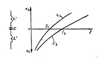
 The high frequency bypass capacitors can filter the high frequency (let the high frequency pass through the branch where the high frequency bypass capacitor is located) and retain the low frequency (low frequency output).For high frequency bypass capacitors, pay attention to the relationship between the size of the inductance contained in the capacitor and the operating frequency. Once a capacitor becomes an inductor, it no longer has the function of bypassing high frequency. All capacitor leads and electrodes contain inductance. The difference is only in the shape of the lead and electrode, which determines the size of the inductance. The figure shows the equivalent circuit of the capacitor and its frequency characteristics. The figure shows two capacitors with the same capacitance (Capacitor 1 and Capacitor 2). Because of their different inductances, they present two different frequency characteristics. The capacitor 1 contains a large amount of inductance. When the frequency rises to f1, the capacitive reactance and the inductive reactance are equal and present in a series resonance state. When the frequency continues to increase, it becomes inductive, which means that the capacitor has become an inductor at this time. The other curve in the figure shows the frequency characteristics of the capacitor 2 with smaller inductance, which can be applied to higher frequency occasions. The parameter that limits the upper limit frequency of the capacitor; the number is the dielectric loss angle lgδ of the capacitor. The size of lgδ depends on the material of the capacitor dielectric. When the frequency of a capacitor with a large lgδ rises, the capacitor will heat up and cause damage. As an anode DC blocking capacitor, a ceramic or mica dielectric capacitor with high voltage resistance and low dielectric loss should be selected.