Aluminum electrolytic capacitor test is very important to ensure the quality of the produced aluminum electrolytic capacitors.
The tests of aluminum electrolytic capacitors mainly include load life test, insulation and grounding, low air pressure test, oscillation, action of pressure relief device, charging and discharging, polarity and reverse voltage, flammability, etc.
By understanding the type test of aluminum electrolytic capacitors, we can know the strict quality inspection of regular aluminum electrolytic capacitors before leaving the factory to ensure the quality of products and the reliability of users.
1.Introduction to the test of the load life of aluminum electrolytic capacitors
Place aluminum electrolytic capacitors in a high temperature box with air circulation. Set the maximum temperature limit to 85°C, 105°C or 125°C with an error of ±3°C. Apply DC voltage and AC ripple voltage. The AC ripple voltage is adjusted so that the rated ripple current is produced, and the DC voltage is adjusted so that the peak voltage of the overlap is equal to the rated voltage of the capacitor. Apply this voltage for a period of 0+6h for the duration of the rated load life cycle. After the test is completed, let the aluminum electrolytic capacitor stabilize at 25°C for more than 24h. Capacitors should meet the limit requirements for capacitance, ESR and leakage current after testing.
2.Aluminum electrolytic capacitor test—load life
Aluminum electrolytic capacitors are subjected to load life time testing in accordance with EIA Standard 479. The gist of this test is as follows: apply a 120Hz ripple current, and adjust to keep the power loss constant if running at other frequencies. Set the DC reference voltage equal to the rated voltage minus the peak value of the AC mains voltage. Set the ambient temperature to 85±2°C, the air velocity to be less than 0.5m/s, and the periodic test interval to be ≤1000h. The number of tested samples is at least 10. Mount the capacitors horizontally with a minimum spacing of 25mm. Select any temperature less than or equal to 85°C to measure all items. During the test, it may appear that the capacitance is less than 80% of the initial value, the ESR is greater than 200% of the initial value, the DCL is greater than the initial value, the shell has obvious mechanical damage or electrolyte leakage, etc.
When more than 10% of the samples have one of the above phenomena, the test ends, and this is the end of life time. There may be 10% of the samples short circuit or open circuit, this phenomenon is not included in it.
3.Aluminum electrolytic capacitor test—insulation and grounding
For aluminum electrolytic capacitors with non-solid electrolyte, the aluminum case is connected to the negative terminal in contact with the electrolyte, resulting in insulation resistance ranging from a few ohms to several thousand ohms. For axial-leaded and surface-mount aluminum electrolytic capacitors, the case is connected to the negative lead. If there are potential components other than the negative terminal in contact with the case, an insulating sleeve should be used. capacitor.
The plastic insulation can withstand a DC voltage of 3000V or an AC voltage of 2500V at 60Hz between the casing and the 1/4in wide metal foil around the sleeve for 1min. For stud-mounting capacitors, apply voltage between the chassis and case, and secure the capacitors with nylon nuts and vias.
After applying 100V voltage to the capacitor for 2 minutes, the insulation resistance between the metal foil and the capacitor shell should be at least 100MΩ. In oscillating or other applications with depletion failure, additional insulation is required.
It should be noted that the heat-shrinkable sleeve of an aluminum electrolytic capacitor is not part of the insulation in principle, and this heat-shrinkable sleeve is easily damaged by heat or other reasons. Short-circuit accident caused by insulation damage for some reasons. Therefore, aluminum electrolytic capacitors must be insulated from the outside world and must be additionally insulated.
4.Aluminum electrolytic capacitor test — low air pressure
The problem discussed here is mainly to test whether the pressure release device of the aluminum electrolytic capacitor malfunctions when the air pressure is low. Aluminum electrolytic capacitors can work at an altitude of 25,000m or 80,000ft, and an environment with air pressure as low as 3kPa. The pressure release device of aluminum electrolytic capacitors should not operate under normal working conditions.
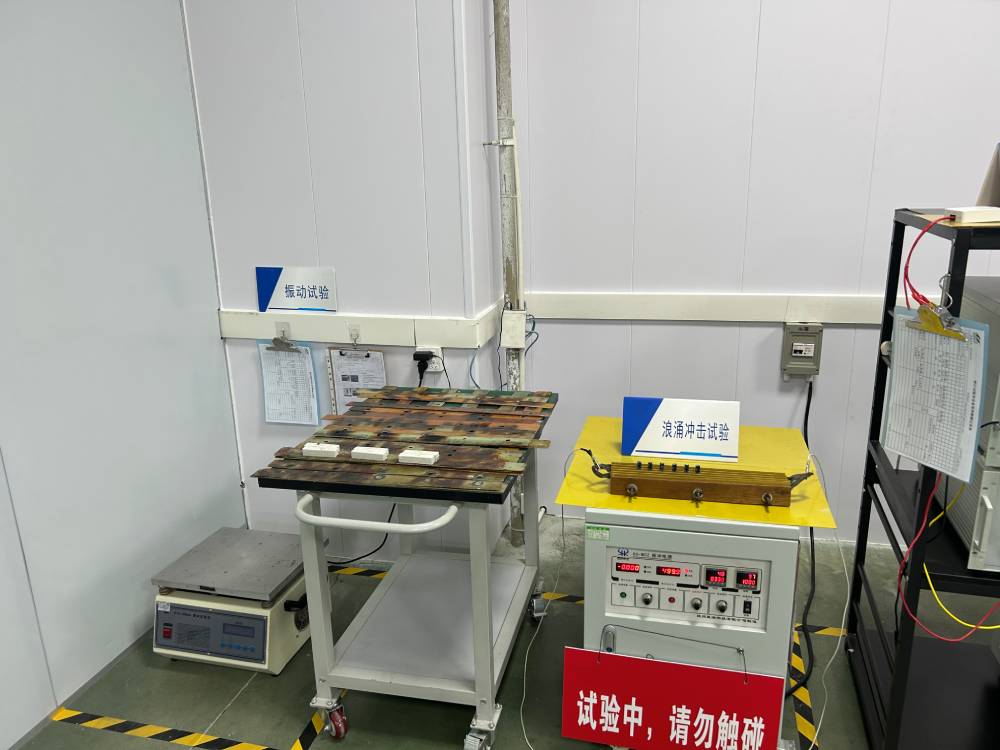
5.Aluminum electrolytic capacitor test – oscillation
Aluminum electrolytic capacitors are typically able to withstand 10g of oscillating force. In order to test the vibration resistance, a set of aluminum electrolytic capacitors is clamped on the vibration platform, and then a set of simple harmonic vibration is applied.
Shake it by hand after the test, the capacitance unit inside the aluminum electrolytic capacitor should not be obviously loose. At the same time, there should be no signs of virtual contact, open circuit or short circuit of the aluminum electrolytic capacitor within the observation period of 3 minutes.
6.Aluminum electrolytic capacitor test — the action of the pressure release device
During the operation of aluminum electrolytic capacitors, the internal gas pressure usually increases. This gas pressure is mainly caused by the hydrogen gas generated during the electrochemical process of repairing the aluminum oxide dielectric film by leakage current. Due to the strong permeability of hydrogen gas, the internal overpressure generated can be released by the penetration of gas through the seal of the capacitor. .
However, internal overvoltage caused by the application of overvoltage, reverse voltage, AC voltage, or internal overvoltage caused by capacitor failure will cause the capacitor to explode. In order to avoid the risk of explosion, aluminum electrolytic capacitors are usually equipped with a pressure relief device. The action of the pressure release device achieves the effect of releasing the gas pressure. The life of the capacitor is terminated after the pressure relief device operates, because the operation of the pressure relief device causes the electrolyte to flow out and dry up.
7.Charging and discharging
If the aluminum electrolytic capacitor is not specially designed for frequent and rapid charging and discharging, the aluminum electrolytic capacitor will be damaged due to overheating or internal overpressure, or the internal circuit will be disconnected or shorted due to circuit failure. For frequent charge and discharge applications, it is necessary to use specially designed aluminum electrolytic capacitors, and do not exceed the charge and discharge speed recommended by the manufacturer.
8.Polarity and reverse voltage
In circuit design and installation, check the polarity of each aluminum electrolytic capacitor. Polarity is marked on the aluminum electrolytic capacitor case. However, in the application of the reverse voltage of the aluminum electrolytic capacitor, it can withstand the reverse voltage below 1.5V, exceeding this value, the aluminum electrolytic capacitor will be damaged due to overheating, internal overvoltage or electrical discharge fault. This can lead to associated open circuits, short circuit failures and rupture of the internal pressure relief holes of the aluminum electrolytic capacitors.
9.Flammability
Aluminum electrolytic capacitors contain substances that can burn and support combustion when exposed to an open flame. Combustible parts include plastic parts, insulating sleeves, insulating paper and electrolyte. Most capacitors will pass the needle-flame test requirements of UL 94V-O, and Class B or Class C products do not support combustion requirements.
In rare cases, aluminum electrolytic capacitors may spontaneously ignite due to severe overloading or during capacitor testing. If the circuit in the aluminum electrolytic capacitor fails and causes electric ignition, the hydrogen gas generated in the electrolytic capacitor will be ignited.