Filter and parallel capacitor fault and protection configuration
AC and DC filters and shunt capacitors are one of the important equipment of the DC transmission system of the converter station. They play an important role in the DC transmission system. They not only provide reactive power for the DC transmission system, but also filter out harmonics on the AC and DC sides. In reality, AC and DC filter faults and parallel capacitor fault can lead to power reduction or DC lockout of the DC transmission system. Therefore, it is a basic requirement for a DC converter station operation and maintenance personnel to correctly understand the importance, protection configuration, and action consequences of AC and DC filters and shunt capacitors. According to the structure, principle, and fault characteristics of AC and DC filters and shunt capacitors, it is very important to correctly configure AC and DC filter protection for the DC transmission system.
1.DC filter fault
The DC filter used in DC transmission is mainly composed of components such as capacitors, inductors, and resistors. The high voltage side of the DC filter is connected to the DC pole bus, and the low voltage side is connected to the neutral bus. If they have a ground fault, in addition to the difference in current between the DC pole line and the neutral line, there will also be a difference in current between the fault filter pole line and the neutral line. In addition, the current through the filter will also increase.
Since capacitor elements are generally composed of multiple capacitors of equal capacity connected in series and in parallel, they can be divided into 2 or 4 groups of equal capacity (currently, converter stations mostly use 4 bridge arm capacitors for distribution). By measuring their unbalanced current, the capacitor fault can be judged. Capacitor failure is the most common type of AC and DC filter failure, accounting for almost more than 90% of this type of equipment. In general, the external manifestation of the failure is the increase of unbalanced current. The internal manifestation of capacitor failure is the breakdown, short circuit or open circuit of the series and parallel components inside a single capacitor. Its internal failure refers to the capacitor failure caused by the breakdown or fuse burnout of one or several components due to manufacturing defects, insulation aging, overvoltage and other reasons. The internal failure of the capacitor is a development process, because when a series component is broken down, the voltage applied to the remaining series components increases accordingly, accelerating the breakdown of the second component. By analogy, whenever a series component is broken down, the remaining components must withstand a higher voltage, and the fault current flowing through the capacitor also increases with the increase of the broken components. It is found from the actual operation of DC transmission projects that if a capacitor symmetry fault occurs, the above measurement will not work. To this end, according to the characteristics of the filter, several characteristic harmonic currents flowing through the filter can be detected, and the detuning degree of the filter can be calculated to judge the fault of the capacitor.
2. AC filter and parallel capacitor fault
Usually, AC filters and parallel capacitors are composed of components such as capacitors, inductors, resistors and lightning arresters. If these components have a grounding fault, there will be a difference in the current between the high voltage and the ground, and the current passing through the filter will also increase. Since capacitor elements are generally composed of multiple capacitors of equal capacity connected in series and in parallel, they can be divided into 2 or 4 groups of equal capacity parts, and the capacitor fault can also be judged by measuring their unbalanced current; in the event of unbalanced current and symmetrical faults that cannot be perceived by measurement, the characteristic harmonic current flowing through the filter can be detected and the detuning degree of the filter can be calculated to achieve the purpose of judging the parallel capacitor fault.
3. Protection of AC and DC filters and parallel capacitor fault
3.1 Protection configuration of DC filter
In the DC converter stations currently in operation, the DC filter protection is mainly configured as follows: overload protection (reactor overload protection, resistor overload protection); capacitor unbalance protection; DC filter differential protection; DC filter harmonic monitoring protection. The DC filter protection configuration diagram is shown in Figure 1.
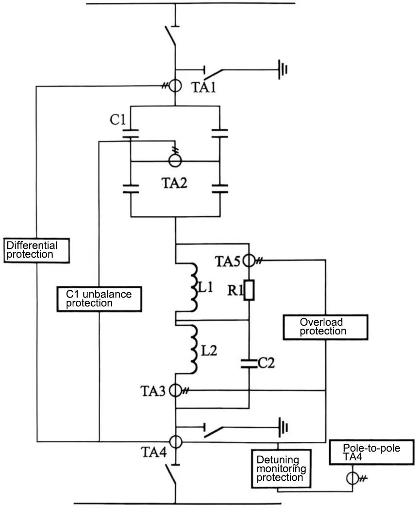
Figure 1 DC filter protection configuration diagram
(1) DC filter overload protection. DC filter overload protection includes reactor overload protection and resistor overload protection. This protection is the component protection of the DC filter, which detects the harmonic current size of the DC filter reactor and resistor to protect the filter components from overstress. The protection has an inverse time characteristic proportional to the square of the current, measures the current passing through each component of the filter group, and compares it with the protection setting value. The tripping has sufficient delay to avoid false operation caused by transient overload protection. The setting of the protection is coordinated with the heat resistance characteristics of the filter components. The protection action is: switch to the redundant control system, disconnect the filter, and if the last set of filters or the fault current is large, lock the converter.
(2) DC filter capacitor unbalance protection. At present, the converter stations in operation in China have capacitor unbalance protection based on two different principles: one is capacitor unbalance protection based on the ratio of unbalanced current to through current; the other is unbalance protection based on direct measurement of the unbalanced current. Both principles are essentially based on the unbalanced current of the capacitor tower as the basic investigation object.
The capacitor bank of the DC filter adopts an H-bridge type or a two-group parallel structure. The capacitor unbalance protection based on the ratio of unbalanced current to through current can be understood as follows: if a capacitor element is short-circuited, the internal fuse will blow to isolate the faulty element, and there will be a small unbalanced current. If the number of faulty capacitor elements increases, the unbalanced current will increase. The purpose of the protection of parallel capacitor fault is to detect capacitor faults, avoid avalanche faults of capacitor units in the DC filter group, and take protective action before the fault develops into avalanche (and retain a certain margin), thereby protecting most capacitors. Its working principle is to measure the unbalanced current of 150, 300 and 600 Hz at the midpoint of the H bridge of the capacitor group. Each unbalanced current is compared with the current of the same frequency flowing through the entire filter. The setting values of alarm and cut-off are based on the ratio of unbalanced current to main current (ITA2/ITA4). Only when the main current of at least two frequencies reaches the setting value, the protection action is allowed. The protection actions are: stage I alarm; stage II alarm and delayed filter cut-off; stage III immediate filter cut-off; if it is the last filter of a pole, the converter is locked.
(3) DC filter differential protection. The purpose of this protection is to detect ground faults within the range of the DC filter. The difference of harmonic current flowing through the filter is measured on the pole side and the neutral side, and compared with the protection setting value. The protection action is to cut off the filter. When the fault current is large or this filter is the last filter of the pole, the converter should be locked.
(4) DC filter harmonic monitoring protection. The purpose of this protection is to monitor the detuning of the DC filter. When both bipolar DC filters are in operation, the 12th harmonic current difference of the bipolar DC filter ITA4 is detected. If it exceeds the set value, an alarm is triggered. When both bipolar DC filters are not in operation, this protection is disabled.
3.2 Protection configuration of AC filter and shunt capacitor
Usually, in end-to-end DC converter stations, AC filters and shunt capacitors are designed in groups, and the filters and shunt capacitors are divided into several large groups, each of which is divided into several small groups of filters and shunt capacitors (back-to-back converter stations generally do not use group design of filters and shunt capacitors due to their low power). This design method of filters and shunt capacitors determines that there are protections for small group filters and shunt capacitors in each group, as well as large group filter protection.
(1) Small group filter protection. The purpose of small group filter protection is to protect each component of the AC filter and shunt capacitor device, such as capacitors, reactors and resistors, from being damaged by overvoltage or overcurrent. The high-voltage capacitor bank is usually arranged in an H-type structure [most of the high-voltage side capacitor banks of converter stations in operation in China adopt an H-type structure, and the high-voltage capacitors of the Hohhot-Liaoning DC transmission project adopt a branch connection method], so as to form an unbalanced protection for the capacitor bank by detecting the midpoint bridge differential current; it is also possible to configure the overcurrent protection of the parallel capacitor and the grounding fault protection of the reactor by detecting the current flowing through the filter, as well as the overload protection of the reactor and resistor thermal detection, the current differential protection of the short-circuit grounding of the parallel reactor, and the filter detuning protection set according to the detection of the zero-sequence current and the impedance value changes of each phase in the filter. For the parallel capacitor fault, these protection measures can effectively prevent the capacitor fault from extending to the entire filter system, thereby ensuring the stability and reliability of the system.
The circuit breaker of the AC filter is an important component that directly affects the operation of the converter station. The small group filter must also be equipped with a circuit breaker failure protection with a reliable detection signal. After the faulty AC filter bank is directly removed by the protection, other filter banks can generally be put into use, which only generates switching disturbances to the operation of the DC system and does not affect normal operation. If there is no backup filter, the DC transmission power needs to be reduced. In this case, the parallel capacitor fault may cause an unbalanced capacitor bank, thus affecting the performance of the overall filter, which requires timely detection and troubleshooting.
Figure 2 is a small group AC filter protection configuration diagram (in which the capacitor unbalance protection adopts the principle of ratio imbalance).
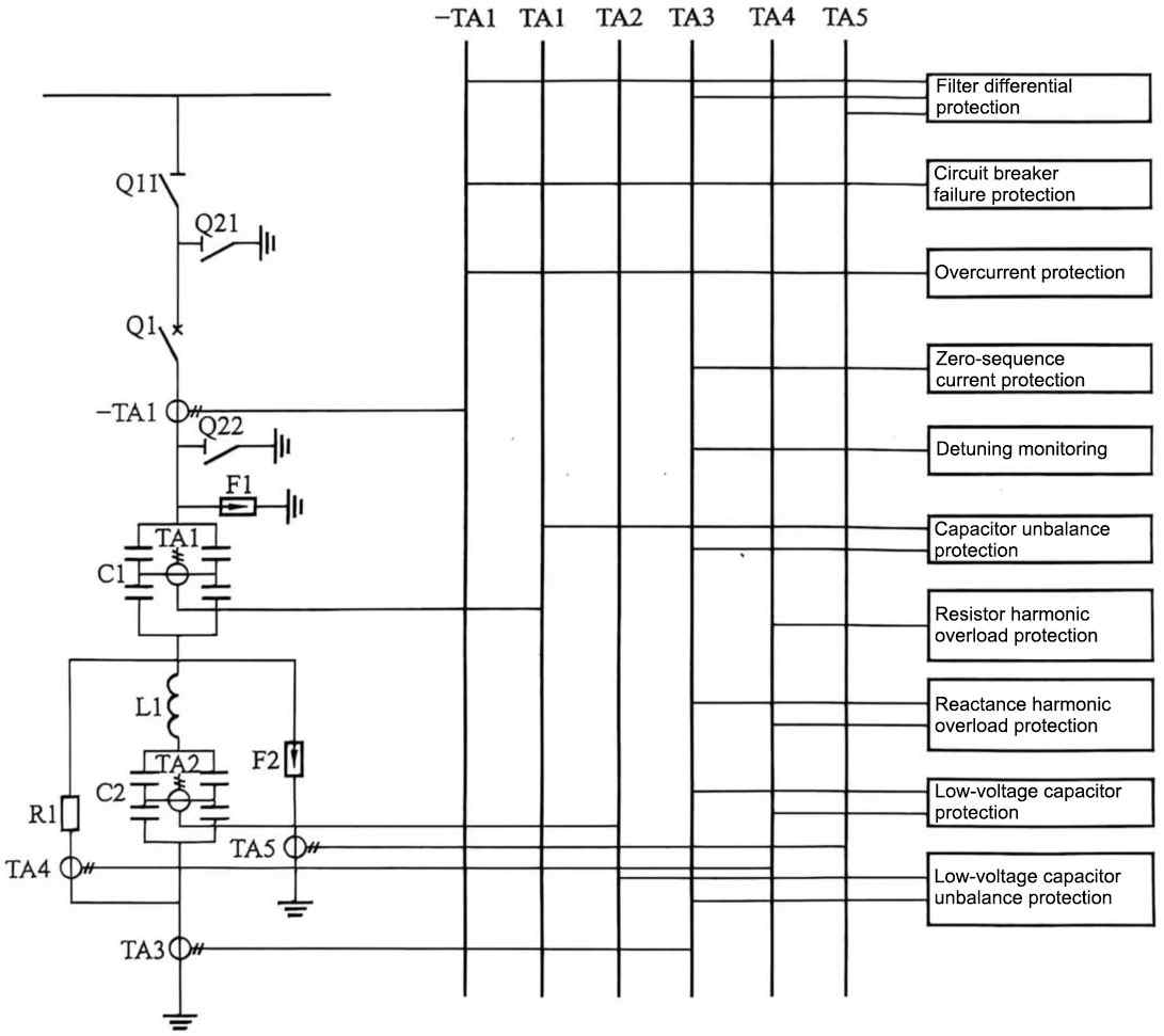
Figure 2 Small group AC filter protection configuration diagram
Since there are a large number of capacitor units in the AC filter and the parallel capacitor group, the failure of a small number of capacitor units has little effect on the filter characteristics. It is often not necessary to immediately cut off the filter group, but different protection measures can be taken according to the number of damaged capacitor units. Its protection measures adopt a three-stage action mode: ① The set value selected in the first section should make the voltage stress on the capacitor element with the highest stress not exceed the designed continuous rated stress under any operating conditions; the first section only sends an alarm signal. If the first section has already alarmed, the filter or capacitor group should continue to operate. ② The set value selected in the second section should make the voltage stress on the capacitor element with the highest stress not exceed the designed continuous rated stress multiplied by the reduced rating factor allowed for another 2h of operation under any operating conditions. In addition, this set value should also be coordinated with overload protection. The second stage should alarm immediately and trip the fault group after 2 hours. If the fault is caused by a parallel capacitor fault, the capacitor unbalance protection detects, when the capacitor of the other capacitor branch also fails, so that the unbalance condition disappears, the timing of the second stage alarm and tripping should not be reset. ③ The setting selected for the third stage should avoid avalanche damage to the capacitor element. The voltage stress on the capacitor element with the highest stress should not exceed twice the designed continuous rated stress. The third stage action should immediately cut off the fault group.
(2) Large group filter protection. The purpose of the large group filter protection is to protect the area from the large group filter incoming line TA to each small group filter TA. The principle and configuration of this protection are largely similar to ordinary AC protection. Its main configurations include differential protection, overcurrent protection, overvoltage protection, failure protection, voltage transformer abnormality protection, etc., as shown in Figure 3.
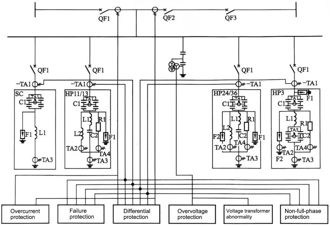
Figure 3 Large group AC filter protection configuration diagram
