1 Frequency Characteristics of Ceramic Capacitor
🍉1.1 Q value and frequency characteristics of ceramic capacitor
The capacitance of the first type of ceramic dielectric capacitors (such as COG) is substantially invariant with frequency over the entire usable frequency range.
Q value and resonant frequency are important indicators when high-frequency/ultra-high-frequency capacitors are used in bad resonant circuits. High-frequency/ultra-high-frequency capacitors with excellent performance have good performance in this regard, such as “Murata”‘s COG dielectric. Ultra-high frequency ceramic capacitors with a capacitance below 10pF have a Q value of more than 1000 meters below 400MHz. In fact, this Q value decreases with the increase of frequency, which can be explained by the increase of loss number with frequency. When the frequency is high to a certain extent, the Q value will drop sharply (the Q value starts to drop sharply after about 6.8pF to above 1.5G), as shown in Figure 3.23, which is also consistent with the increase of ESR with the increase of frequency.
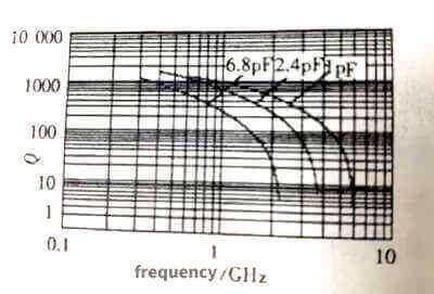 Figure 3.23
Here, “ultra-high frequency” mainly means that it can work at ultra-high frequency, and of course it can also work at various frequencies below ultra-high frequency. As can be seen from the figure, the characteristic shifts to the left as the capacitance increases. In fact, the discussion of larger capacitance will be meaningless at ultra-high frequency. For example, the 1000pF capacitive reactance is only 0.318Ω at 1GHz, while the inductance of the 1cm lead is 10nH, and the resonance frequency with the 1000pF capacitor is about 50MHz, which is 1 at 1GHz. /20, that is to say, a capacitor of 1000pF is used for a resonant circuit, and its resonant frequency generally does not exceed 50MHz. At a frequency of 1MHz, it can only be used for filtering or bypassing. This is the Q value and it is meaningless.
🍇1.2 Resonant frequency, ESR and impedance frequency characteristics
Any capacitor has its own resonance frequency, that is, the frequency at which its own capacitance and parasitic inductance form series resonance. In the same package, the parasitic inductance is basically the same. Naturally, the larger the capacitance, the lower the resonant frequency, as shown in Figure 3.24, and the smaller the package size, the higher the resonant frequency.
The ESR of the first type of ceramic dielectric capacitors increases with frequency, as shown in Figure 3.24, and as the frequency decreases, the ESR characteristics gradually flatten.
The ESR of the first type of dielectric, such as COG dielectric capacitors, decreases with the increase of capacitance, as shown in Figure 3.25. The reason is obvious. As the capacitance increases, the area of the plate also increases. Under the same packaging conditions, only It can be obtained by increasing the number of layers of polar plates. Since the ESR of each layer of polar plates is basically the same, the number of parallel polar plates increases, and the ESR will inevitably decrease.
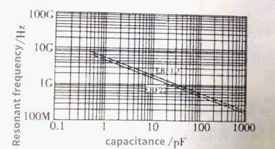 Figure 3.24
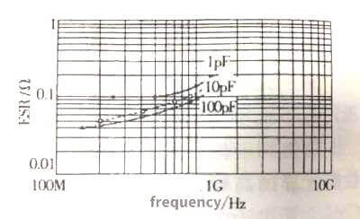 Figure 3.25
The relationship between ESR, capacitance and frequency of C0G dielectric ceramic capacitors is shown in Figure 3.26. The impedance frequency characteristics are shown in Figure 3.27.
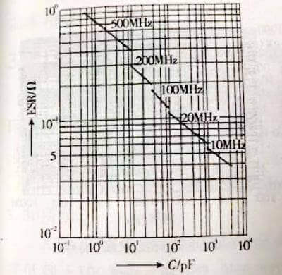 Figure 3.26
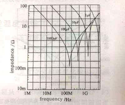 Figure 3.27
Characteristics can be divided into three parts: capacitive part, resonant part, inductive part. In the capacitive part, the capacitor exhibits capacitor characteristics, which is consistent with: Xc=(1πƒ·C)-1, and the impedance decreases with the increase of frequency, as shown in the left half of the curve in Figure 3.27. In the resonance part, the inductive reactance of the parasitic inductance of the capacitor increases with the frequency to a level close to the capacitive reactance. Since the inductive reactance and the capacitive reactance have opposite signs, the actual impedance of the capacitor in this frequency band is smaller than the capacitive reactance of the capacitor. When the inductive reactance is equal to When the capacitive reactance is in the resonance state, the capacitive reactance is canceled by the inductive reactance, leaving only the ESR, as shown in the steep drop of impedance in the characteristic curve in Figure 3.27. As the frequency further increases, the inductive reactance begins to be larger than the capacitive reactance, and the capacitor begins to gradually behave as an inductive characteristic, as shown in the rising part on the right side of the characteristic curve in Figure 3.27.
The impedance frequency characteristics of ceramic capacitor the second type of dielectric capacitors are shown in Figure 3.28. Similar to the first type of dielectric capacitors, the characteristics of ceramic capacitor can also be divided into three parts: capacitive part, resonant part, and inductive part. The shape of the characteristics of ceramic capacitor curve is also basically the same. Different from the first type of dielectric capacitors, the capacitance of the second type of dielectric capacitors is generally much larger than that of the first type of capacitors, and the frequency band where the characteristic curve is located is lower than that of the first type of dielectric capacitors. For example, the resonance frequency of a capacitor with a capacitance of 10nF is about 50MHz, the resonance frequency of a capacitor with a capacitance of 100nF is reduced to less than 20MHz, and the resonance frequency of a capacitor with a capacitance of 10UF is reduced to 2MHz.
Similar to the first class of dielectric capacitors, as the capacitance increases, the ESR also decreases. The difference is that the frequency characteristics of ESR have changed. Taking the 50V/10UF capacitor of X5R dielectric as an example (the right side of Figure 3.28), the ESR in the low frequency band decreases with the increase of frequency, about 100kHz, in the range of 100kHz to 1MHz. The ESR of 1MHz is reduced to the lowest value, and the ESR of the frequency band above 1MHz increases with the increase of frequency.
The-frequency-and-temperature-characteristics-of-ceramic-capacitors.jpg)
 Figure 3.28
Figure 3.28
As can be seen from the figure on the right side of Figure 3.28, the ESR of the 50V/10UF Type II ceramic capacitor is only 5mΩ, which is also an extremely low ESR value among various electrical appliances.
🍓1.3 Frequency characteristics of loss factor
The relationship between loss factor and frequency: The loss factor of the first type of ceramic dielectric capacitor increases with the increase of frequency. The relationship between the loss factor of the first type of COG dielectric, capacitance and frequency is shown in Figure 3.29. Increasing the capacitive reactance decreases, so that the loss factor of the capacitor increases with the increase of the capacitance at the same frequency. The dissipation factor of capacitors of the same capacitance increases with frequency. In fact, the dielectric loss of COG media does not vary with frequency within the application frequency. The reason why the loss factor increases with frequency is that when the loss factor is measured under the condition that the terminal voltage of the capacitor is constant, as the frequency increases, the capacitor current increases, so the loss generated in the capacitor’s ESR also increases. When the frequency is higher than a certain value, the loss generated by the ESR becomes the main loss, and the loss factor at this time will increase linearly with the frequency.
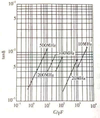 Figure 3.29
The variation characteristics of the loss factor of the second type of ceramic dielectric capacitors with frequency are basically similar to those of the first type of dielectrics, and will not be repeated here.
2 Temperature characteristics of ceramic capacitors
For ceramic capacitors, in addition to temperature affecting capacitance, there are insulation resistance, dissipation factor, etc.
🍒2.1 Insulation resistance of ceramic capacitor
The insulation resistance of X7R dielectric ceramic capacitor changes relatively greatly with temperature, as shown in Figure 3.30.
The insulation resistance of X7R dielectric ceramic capacitors decreases from 4000s (or Ω.F) at about +15°C to a little over 120s at +100°C; the insulation resistance of Y5V dielectric ceramic capacitor changes with temperature than that of X7R, as shown in Figure 3.31 .
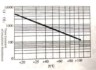 Figure 3.30
 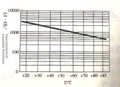 Figure 3.31
Insulation resistance drops from 2700s (or Ω.F) around +20°C to a little over 300s at +80°C. The insulation resistance of the two is basically the same, but lower than that of C0G. From the relationship between insulation resistance and temperature, in high temperature applications, attention should be paid to whether the insulation resistance of the capacitor meets the requirements.
🍑2.2The relationship between the dissipation factor and temperature of the second type of ceramic dielectric capacitors
The dissipation factor of the second type of ceramic dielectric capacitor is significantly higher than that of the first type of dielectric, and it varies more with temperature. The dissipation factor of X7R dielectric ceramic capacitors decreases as the temperature rises, from about 4.5% at -55°C to 1% at +125°C, and it hardly changes with temperature between 50 and 70°C. The dissipation factor of Y5V dielectric ceramic capacitors decreases with temperature, from about 12% at -20°C to less than 1% at +85°C, of which it hardly changes with temperature between 50 and 85°C. When the temperature is lower than normal temperature, the loss factor of X7R is obviously smaller than that of Y5V, and the loss factor of X7R is smaller than that of Y5V at normal temperature.
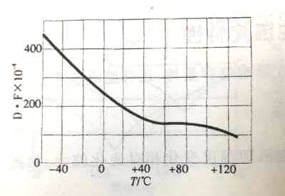 Figure 3.32
  Figure 3.33