Electrolytic capacitors aluminum foil corrosion process is widely used in industrial production.In actual industrial production, the tunnel corrosion process is generally used, including the steps of pre-stage chemical treatment → pre-stage electrolytic corrosion → post-stage electrolytic corrosion → post-stage chemical treatment.
1 Tunnel etching process
☘️1.1 Pre-chemical treatment
The annealed electrolytic capacitors electrolytic capacitors aluminum foil sample generally has a certain thickness of natural oxide film, oil stains and other pollutants on the surface.In order to remove the heterogeneity on the surface of the sample, activate the surface state of the sample, which is conducive to the uniform distribution of corrosion holes, the sample must be soaked in acid or alkali solution.
🍀1.2 Pre-stage electrolytic corrosion
This is the key step of the entire etching process. In this step, it is required that the etched holes are uniformly initiated and grown to a certain diameter and depth. The hole density is too dense. During subsequent hole expansion, the surface of the sample is eroded or the oxide film is energized by high voltage due to the occurrence of merging of the holes or the too small interval between the holes. All of them drop sharply; if the pit density is too thin, the specific capacitance value is too low. Therefore, reasonable control of the pit initiation density and the uniformity of the pit distribution is the core issue.
🎍1.3 Post-stage electrolytic corrosion
The samples corroded by the previous stage have etched holes with a certain density, pore size and depth on the surface, but the pore size is generally too small to meet the requirements of high-voltage energized oxide films, and the hole depth has not reached the optimum state. Therefore, the pre-corrosion samples should be expanded, which not only expands the pore diameter, but also deepens the hole depth.
The pre-corrosion can form a conversion film. After the pre-corrosion, there should be a thin conversion coating protective layer on the surface of the sample and the wall of the etched hole, which is still effective in the subsequent hole expansion corrosion process. The pit density on the surface of the sample has reached the requirement, so it is not necessary to initiate new pits in the subsequent etching process, so as to avoid the pit density being too high and the pit merging or the pit interval being too small. Therefore, in general, the corrosiveness of the back-stage corrosion electrolyte is greatly weakened compared to the front-stage corrosion electrolyte, and the concentration of the corrosive agent can also be reduced. In addition, since there is still a protective layer of conversion coating on the surface and pore wall of the sample after the previous stage corrosion, it is not necessary to add an oxidant or a corrosion inhibitor to the electrolyte for the subsequent stage corrosion to prevent the surface of the sample from being eroded.
It is worth noting that in the post-corrosion process, the growth rate in the depth direction of the etched hole and the growth rate of the pore diameter should be reasonable, and the speed in the concentration direction is too fast, causing the etched hole to penetrate through the electrolytic capacitors aluminum foil. Although the specific capacitance is improved, the strength is difficult to guarantee. On the contrary, it is lower than the capacitance. If the speed in the aperture direction is too fast, the pits will merge or be eroded; if it is too slow, the voltage energization requirements will not be met. Therefore, the etchant concentration, liquid temperature and current density must be reasonably selected for the subsequent corrosion.
🎋1.4 Post-stage chemical treatment
Since there are still conversion films or segregated Cu, Fe and other impurity elements and residual compounds on the surface and pore walls of the sample after the subsequent hole expansion corrosion, these substances are harmful components for the manufacture of electrolytic capacitor anodes and should be removed. The post-stage chemical treatment generally adopts the method of soaking in HNO3 solution.
To sum up, a complete tunnel corrosion process and generally used conditions are shown in Figure 3-25
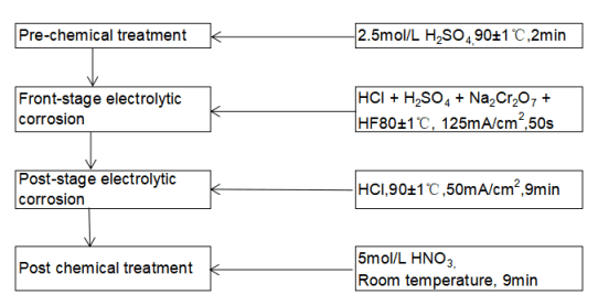 Figure 3-25
🍄2. Laboratory static test of electrolyte composition
Before the official production, the laboratory static test must be carried out, and the composition of the pre-corrosion electrolyte is the most critical test parameter. According to the discussion in Section 3.2, aluminum foil has good pit initiation and productivity in the mixed solution of HCI, H2SO4, CrO3 and HF. It should be pointed out that actual industrial production is different from laboratory research, and the related consideration of cost is very important. Therefore, it is considered here to replace Cr03 with Na2 Cr2 07 with similar chemical properties but lower unit price.
Figure 3-26 shows the relationship between the specific capacitance and the addition of different concentrations of Na2 Cr2 07 . The specific capacitance shows a maximum value at 0.4 moI/L with the change of Na2 Cr2 O7 concentration. When the concentration of Na2 Cr2 O7 is lower or higher than 0.4 moI/L, the specific capacitance shows a downward trend. This is because, when the concentration of Na2 Cr2 O7 is very low (Fig. 3-27(a)), due to the thin conversion film formed on the surface of the electrolytic capacitors aluminum foil, the protection ability to the surface of the electrolytic capacitors aluminum foil is weak, so a large number of pits are merged, which leads to the Capacitance is low. When the concentration of Na2 Cr2 O7 is 0.4moI/L (Fig. 3-27(b)), the thickness of the conversion coating is moderate, and the protection ability to the surface of the sample is moderate, and the initiation and growth of corrosion holes are mainly affected by the pores of the conversion coating. The film structure is dominated, and the current is mainly distributed at the pore film of the conversion film, so that the distribution of the etched holes is relatively uniform, and the merging of the etched holes does not occur, so the specific capacitance is higher. However, when the concentration of Na2 Cr2 O7 is further increased (Fig. 3-27(c)), the formed conversion film Baidu is too large. Since the formation of the conversion film is related to the dissolution reaction of aluminum, the greater the thickness of the conversion film, the greater the amount of aluminum dissolved, the pore size of the etched hole increases, and the etched hole density decreases, resulting in a decrease in specific capacitance.
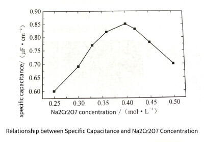 Figure 3-26
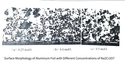 Figure 3-27
HF is another important component in the etching solution. When the chromate conversion film is formed on the aluminum surface, the natural oxide film on the aluminum surface can greatly promote the formation of the conversion film on the aluminum surface due to the dissolution of fluoride ions. Figure 3-28 shows the change of specific capacitance with HF concentration. Similar to the case of Na2 Cr2 O7, the specific capacitance shows a maximum value when the HF concentration is 0.1moI/L.
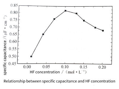 Figure 3-28
This is because when the added HF concentration is low, due to the poor dissolving ability of HF to the natural oxide film on the aluminum surface, the formed conversion film is not uniform, and the distribution of corrosion holes caused by it is not uniform, so the specific capacitance of the electrolytic capacitors aluminum foil is low; When the added HF concentration is too high, it is not difficult for HF to dissolve the natural oxide film on the aluminum surface, and also dissolve the electrolytic capacitors aluminum foil matrix, resulting in a significant decrease in the Baidu of the electrolytic capacitors aluminum foil. As a result, the etched holes are too dense, and even the etched holes merge, thereby reducing the specific capacitance of the sample. Only when the concentration of HF is moderate, HF only dissolves the natural oxide film on the aluminum surface, promotes the good formation of the conversion film, the distribution of the porosity is relatively uniform, and the specific capacitance value of the sample is the largest.
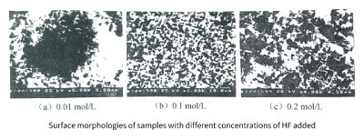 Figure 3-29
🍁3. Design of pilot production line
In order to transform scientific research results into real productivity and transition from laboratory samples to mass-produced products, it is necessary to design pilot production lines. Figure 3-30 shows the schematic block diagram of the pilot production line for aluminum foil corrosion.
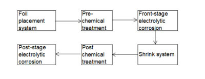 Figure 3-30
🍂3.1 Design principles
The design of the pilot production line follows the following principles:
(1) The pilot production line is a dynamic test of the experimental static test. First, its process should be designed according to the static test process; secondly, the dynamic conditions of each part of it should be consistent with the static test. Thereby ensuring that the static test results in the laboratory can be of high importance under dynamic conditions.
(2) The pilot production line is the prototype of the industrial production line. The industrial production line requires that the process must have good operability, which requires that the process conditions of the pilot production line should be adjustable in a wide range.
(3) The pilot production line is not only a small industrial production line, but also a dynamic test method for new process research, with duality of production and scientific research.
🍊3.2 Key issues
The pilot production line needs to focus on solving the following problems:
(1) The problem of reconciling the electrolyte. The pre-stage chemical treatment, pre-stage electrolytic corrosion, post-stage electrolytic corrosion and post-stage chemical treatment on the pilot production line are all carried out in the corrosion-resistant tank body. In addition to being affected by the reaction process, the composition of the electrolyte in each tank is mainly determined by the corresponding blending system. The composition of the electrolyte is related to the treatment and corrosion effect in each tank and determines the final corrosion result. Therefore, the reconciliation system of the electrolyte plays an important role. In order to ensure the stability of the electrolyte composition, we have designed an automatic adjustment system for the electrolyte.
(2) The composition balance of the electrolyte. With the progress of the pilot test, different chemical or electrochemical reactions occur in each cell, causing the composition of the electrolyte to change. In order to maintain the balance of electrolyte components, it is necessary to supply new liquid and discharge old liquid. According to Faraday’s law of electrolysis, the supply flow j(L/S) can be deduced as
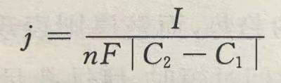
In the formula: I is the current value (A) applied by the electrolytic cell, n is the number of electrons participating in the electrolysis reaction, F is the Faraday constant, and C1 and C2 are the concentrations of the supply and overflow ports (moI/L), respectively. For reactant ions, ∣C2-C1∣=C1-C2; for product ions, ∣C2-C1∣=C2-C1 .
Accordingly, we designed an automatic replenishment and overflow system.
(3) The composition balance and temperature balance of the electrolyte. When the electrolytic capacitors aluminum foil reacts in the tank, the composition and temperature of the electrolyte near the electrolytic capacitors aluminum foil are different from those of other parts of the tank; the composition and temperature of the electrolyte are partially unbalanced, which in turn affects the speed of the reaction. . Aiming at the local imbalance phenomenon, we designed an automatic circulation system of the electrolyte.
(4) The problem of local adjustment of reaction time. The reaction time of electrolytic capacitors aluminum foil in each reaction tank can be proportionally increased or decreased by adjusting the system speed of the pilot production line, which makes it difficult to adjust the reaction time in a certain tank individually. A time adjustment system is designed.
(5) Current ripple suppression problem. In order to maintain a constant corrosion amount during the dynamic corrosion process, the applied current ripple coefficient must be suppressed below 1%. The corrosion power supply of the pilot production line is a low-voltage high-current (2500 A, 4V) DC power supply, and the usual filtering methods cannot meet the requirements, so we designed a special filtering system.
(6) The problem of tank pressure regulation. In the static test, since the solution cannot be stirred, the aluminum ions dissolved on the electrolytic capacitors aluminum foil can only diffuse from the aluminum foil to the tank liquid through the diffusion mass transfer process, and the ions in the tank liquid participating in the reaction can only be transferred from the tank through the diffusion mass transfer process. The liquid moves to the aluminum foil interface, resulting in a concentration gradient of reactant and product ions near the aluminum foil bath liquid interface, and these two concentration gradients cause concentration polarization near the interface. Under constant current conditions, the cell voltage increases. However, in the dynamic test, due to the action of the electrolyte automatic circulation system, the convective mass transfer process in the tank is increased; thus the moving speed of the reactants and product ions is increased. The above two concentration gradients can be ignored. Transformation does not exist. Therefore, under the same corrosion conditions, the static test cell voltage of the dynamic test is low.
(7) Tension control problem. When the aluminum foil is corroded on the pilot production line, it is always under tension. The aluminum foil will undergo elastic deformation under the action of tension, and the elastic deformation will generate elastic strain energy inside the aluminum foil, and the change of tension will cause the change of strain energy. The existence of elastic strain energy causes stress corrosion of aluminum foil, and a certain tension helps to improve the specific capacitance of the corroded foil; however, excessive stress will not be conducive to improving the specific capacitance or even reducing the specific capacitance. Therefore, the tension of the aluminum foil should be monitored, and an automatic tension monitoring system is generally used.
🍋3.3 Parameter adjustment
During the pilot production line test, the composition of the electrolyte, the temperature of the bath and the applied current density were consistent with the static test. The main adjustable parameters were the system speed (vehicle speed) and the replenishment flow, which could change the reaction time and bath respectively. The concentration of ions or aluminum ions involved in the reaction.
Figure 3-31 shows the specific capacitance and foil thickness at different vehicle speeds. With the increase of vehicle speed, the corrosion time of the front and rear stages decreases proportionally, the specific capacitance shows a trend of increasing first and then decreasing, while the thickness of the foil shows a law of first increasing rapidly and then tending to remain unchanged. It can be seen from the previous discussion that when the corrosion time of the current stage is too short, the corrosion holes are distributed in clusters, and there are obvious uncorroded areas. Therefore, when the vehicle speed is greater than 1.4m/min, the specific capacitance is relatively small, and the specific capacitance increases sharply with the vehicle speed. On the contrary, when the vehicle speed is lower than 1.4m/min, the pitting caused by the previous stage is oversaturated, and increasing the pitting initiation time can only make the pitting too dense. After stage reaming, the etched holes are merged and even the surface is eroded, so the specific capacitance shows a maximum value and the foil thickness decreases.
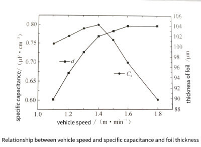 Figure 3-31
Figure 3-32 shows the relationship between the front-stage corrosion flow rate and specific capacitance and foil thickness. It can be seen from formula (3-26) that there is an inverse relationship between the flow and the concentration difference of a certain ion in the tank at the replenishment port and the overflow port. In the front-stage corrosion tank, the ions participating in the reaction are Cr2 and Cr, and the generated products are A and C, and the concentration of Cr2 and C at the supply port is a fixed value, and the concentration of A and C is zero, so the flow value can approximately reflect the overflow The concentration of Cr2 , A , and C at the orifice can also be approximately considered to be equal to the ion concentration in the tank. Therefore, an increase in flow rate leads to an increase in the concentration of Cr2 and ions in the bath, while the concentration of A and C ions decreases.
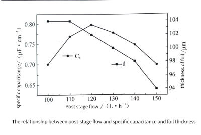 Figure 3-32
Figure 3-33 shows the relationship between the flow rate of the latter stage and the specific volume and foil thickness. For the post-stage corrosion, the ions participating in the reaction are only A, and the product ion is only A. When the post-stage flow rate is small, the concentration is low, the A concentration is high, the hole enlarging effect is poor, and the specific capacitance is low. When the flow rate is large, the concentration is high, but the A is low. At this time, the conversion film of the previous stage corrosion is dissolved, resulting in ablation, so the foil thickness is reduced and the specific capacitance is low. Only when the flow rate of the rear stage is moderate, the hole reaming effect is the best, the specific capacitance is the largest, and the foil thickness is slightly reduced.
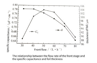 Figure 3-33
🍉3.4 Product Instructions
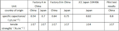
Table 3-3 gives a list of the comparison between the pilot test results and similar products at home and abroad. It can be seen from the table that the technical indicators of the corroded foil obtained from the pilot test have reached the international advanced level. This result lays a solid foundation for my country to get rid of the situation that high specific capacitance and high voltage anode foil has been relying on imported aluminum foil for production until the end of the 1990s, and change the domestic long-term dependence on imported corrosion equipment and technology. The corresponding patented technology products have achieved significant economic benefits in the subsequent production, and the research results won the third prize of the 1996 National Science and Technology Progress Award.
🍓4. New progress in aluminum foil corrosion technology
4.1Frequency conversion corrosion technology
In the past, most of the voltage corrosion technologies directly use 50Hz power frequency alternating current. The advantage is that no additional treatment of the power supply is required, but the corrosion depth is not easy to control, and the corrosion uniformity is poor, resulting in insufficient increase in the effective surface area of the corrosion foil and poor tensile strength. The capacitors it produces are lower than the capacitance. In recent years, the frequency conversion power supply has been gradually introduced into the corrosion process. Since the frequency of the power supply can be lowered after the frequency conversion, the corrosion uniformity is improved, and the specific capacitance of the corrosion foil is greatly improved.
There are two key technical points in the frequency conversion corrosion technology: first, the corrosion power supply not only needs to change the frequency of the power supply, but also needs to control the output waveform, generally an asymmetric sine wave is preferred; The chemical corrosion rate of the electrode foil reduces ineffective corrosion.
By means of frequency conversion corrosion technology, the current production of low-voltage foils has begun to develop from power frequency low-speed corrosion technology (2 ~ 3m/min) to frequency conversion high-speed corrosion technology (5 ~ 8m/min). The basic process flow is: pretreatment → – secondary corrosion → intermediate treatment → secondary corrosion → intermediate treatment → 10 to 14 times of corrosion → cleaning → post-treatment → cleaning → drying. The key step parameters are as follows:
Pretreatment: 1~2moI/L HCI, H2SO4, H3PO4, etc., temperature 30~70℃, duration 1~2min.
Corrosion: 2~4moI/L HCI+0.01~0.1moI/L H2SO4 , temperature 15~30℃, frequency 10~35Hz.
Post-treatment: 1 moI/L HNO3, temperature 50~70℃, duration 1~3miN.
🍈4.2 Multiple pore corrosion technology
With the continuous improvement of the specific capacitance of the high-voltage electrode foil, the thickness of the electrode foil is also increasing, from the previous 104um to the current mainstream 130um. After the thickness of the electrode foil increases, the efficiency of the traditional single-shot low-speed (less than 2m/min) etching technology decreases, and it can no longer meet the production needs gradually. In order to adapt to the increase in the thickness of the electrode foil and improve the production efficiency, the high-speed (4-7m/min) etching technology of multiple perforations has been applied in production. /(Enable voltage 528V) increased to 0.8UF/(Enable voltage 540V)
There are three key technical points in the multiple porosity corrosion technology: first, proper surface treatment is required before and after each porosity; second, the corrosion process temperature is low, which reduces the chemical corrosion rate of the electrode foil and reduces ineffective corrosion; third , the corrosion groove is deepened, and the time of exposure to the air during the corrosion process of the aluminum foil is reduced. The typical process flow is: pretreatment→-secondary hole→second hole→intermediate treatment-→third hole→fourth hole→intermediate treatment two→fifth hole→cleaning→7-9th stage reaming→ Washing→post-processing→drying. The key step parameters are as follows.
Pretreatment: 1~2moI/L HCI, H2SO4, temperature 30~70℃, duration 1~2min
Five times of pores: 5~8moI/L HCI, H2SO4+0.5~1.5moI/L HLI, temperature 60~80℃, current 3000~5000A
Duration 30~60s
Intermediate treatment: 5~7moI/L HCI or H2SO4, temperature 70~90℃, duration 30~60s;
Reaming: 1~2moI/L HNO3+trace H3PO4, temperature 60~80℃, current 3000~5000A
Duration 30~90s
Post-treatment: 1moI/L HNO3 temperature 50~70℃, duration 1~3min