A parallel plate capacitor is composed of two parallel metal conductor plates, separated by a dielectric material in the middle. When there is a certain potential difference between the two plates, there will be an electrostatic field distribution between the plates. There is a uniform electric field distribution between the two plates. Due to the edge effect, the electric field lines at the edge of the capacitor are bent and divergent. The parallel plate capacitor is the simplest capacitor. Any non-parallel plate capacitor can be regarded as a series and parallel connection of several small parallel plate capacitors.
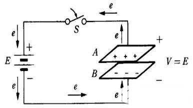
In the figure, A and B are parallel conductive electrode plates, which are separated by insulating materials (such as air) and connected to a DC source E via a switch S. Both pole plates remain neutral before being powered on. When S is closed, the electrons of plate A are attracted to the positive electrode of the battery, so A is positively charged; at the same time, the electrons at the negative end of the battery are repelled to plate B, making B appear negatively charged; therefore, An electric field is formed between the A and B plates and a potential difference V is established. This phenomenon of electron flow continues, and the transferred amount of electricity is proportional to the voltage of the power supply. The movement of electrons is stopped until the potential difference between the AB plates is equal to the power supply voltage (V = E). During the flow of electrons, the energy of the power source is taken out and stored on the two plates, that is to say, electric charge is stored.
Parallel-plate capacitors are the simplest and most practical capacitors. A dielectric is filled between two plates. The distance d between the two plates is much smaller than the area A of the plates, as shown in the figure.


