1 Principle of aluminum electrolytic capacitors and implementation method of large capacitance
When converting AC into DC, capacitor filtering is usually required to smooth the rectified DC, and a capacitor with a large capacitance is required to smooth the DC voltage from zero to peak (1.414 times the effective value) into a nearly smooth DC voltage. Taking a single-phase bridge rectifier as an example, in the capacitor input filter circuit, the capacitor plays a key role in the smoothing process, especially the application of the principle of aluminum electrolytic capacitors, which enables the capacitor to achieve a larger capacitance. Generally, each rectifier diode can only conduct for about 3ms to supply power to the output, and the output is powered by the filter capacitor for the remaining 7ms. At this time, the energy storage of the capacitor will fluctuate by about 20%, that is, the capacitor provides 20% of the energy storage to the output for every half power cycle, corresponding to 70% of the output power.
![]() (1)
(1)
![]() (2)
(2)
When ƒ is 50Hz:
![]() (3)
(3)
![]() (4)
(4)
Take the AC 220V input directly rectified output voltage peak of about 300V, and supply power to 100W load as an example, the required capacitance is
![]() (5)
(5)
about 80µF, the size and price of a 80µF/400V film capacitor are difficult to accept.
For example, how big a filter capacitor is needed for a rectifier that supplies 15V/1A (the rectifier needs to have a voltage of 20V before the voltage regulator circuit, and a power of 20W)?
![]() (6)
(6)
It is almost impossible to find a 3300µF/25V film capacitor!
For the above reasons, it is necessary to seek a capacitor with large capacitance, small size and low price, which is the principle of aluminum electrolytic capacitors. How does an electrolytic capacitor achieve a large capacitance? First of all, the effective area of the plate must be increased. The method to increase the effective area of the plate in an electrolytic capacitor is to corrode the aluminum foil of the positive electrode to a very rough corrosion foil or sinter the tantalum metal powder into a block structure to increase the surface area as much as possible. However, in fact, the effective area of the plate cannot be increased by simply increasing the rough positive electrode surface area and the metal negative electrode. Only when the negative electrode substrate is as rough as the positive electrode and the surfaces of the two electrodes are in close contact everywhere can the effective increase of the plate area be achieved, which is actually impossible to achieve. To achieve close contact between positive and negative electrodes under a rough surface, one electrode can only be a solid metal, and the other electrode can only be a non-solid state, or a way to make such a negative electrode, such as a conductive liquid or gas. Considering that the conductivity of gas is far less than that of liquid, this electrode should be a conductive liquid, so that the area of the two electrodes can be much larger than the geometric area of the electrodes, greatly increasing the capacitance. The next question is the medium. What kind of medium can change arbitrarily with the rough metal electrode? Obviously, inserting a thin film medium is definitely not an option. There is a type of metal called valve metal. This type of metal can be used to obtain an oxide film with good insulating properties through anodic oxidation to form the medium of the capacitor. This type of metal includes aluminum, tantalum, niobium, and titanium. In this way, the characteristics of aluminum or tantalum anodizing methods to form a dense oxide film on the surface can be used, and aluminum oxide and tantalum oxide films can be used to form insulating media. Since aluminum oxide and tantalum oxide have high insulation strength and large relative dielectric constant [relative dielectric constant is 8 for aluminum oxide and about 20 for tantalum oxide, which is much higher than the dielectric constant of general films (2~3)], the capacitance of aluminum electrolytic capacitors and tantalum electrolytic capacitors can be hundreds of times that of general capacitors, and it is easy to obtain hundreds or even hundreds of thousands of microfarads of capacitance, which is not possible for general film capacitors.
2 Basic knowledge of aluminum electrolytic capacitors
2.1 Structure
Usually, in the principle of aluminum electrolytic capacitors, aluminum electrolytic capacitors are formed by winding the intersection of anode aluminum foil, cathode aluminum foil and isolation paper, as shown in Figure 1, and then soaked in liquid electrolyte, connected with terminal wires (or bolts) and installed in a container. Among them, the anode aluminum foil is high-purity aluminum etched in thousands of tiny tunnels to increase the contact area with the electrolyte. Figure 2 shows the microstructure of the anode aluminum foil after corrosion processing.
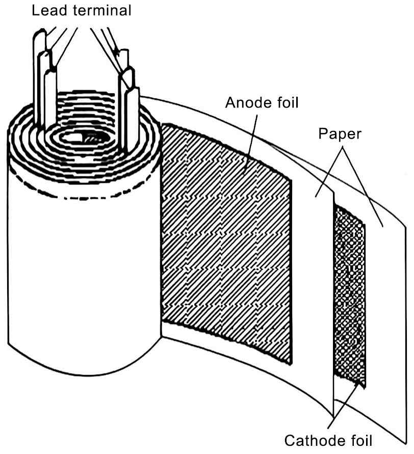
Figure 1 Schematic diagram of the structure of the winding structure electrolytic capacitor
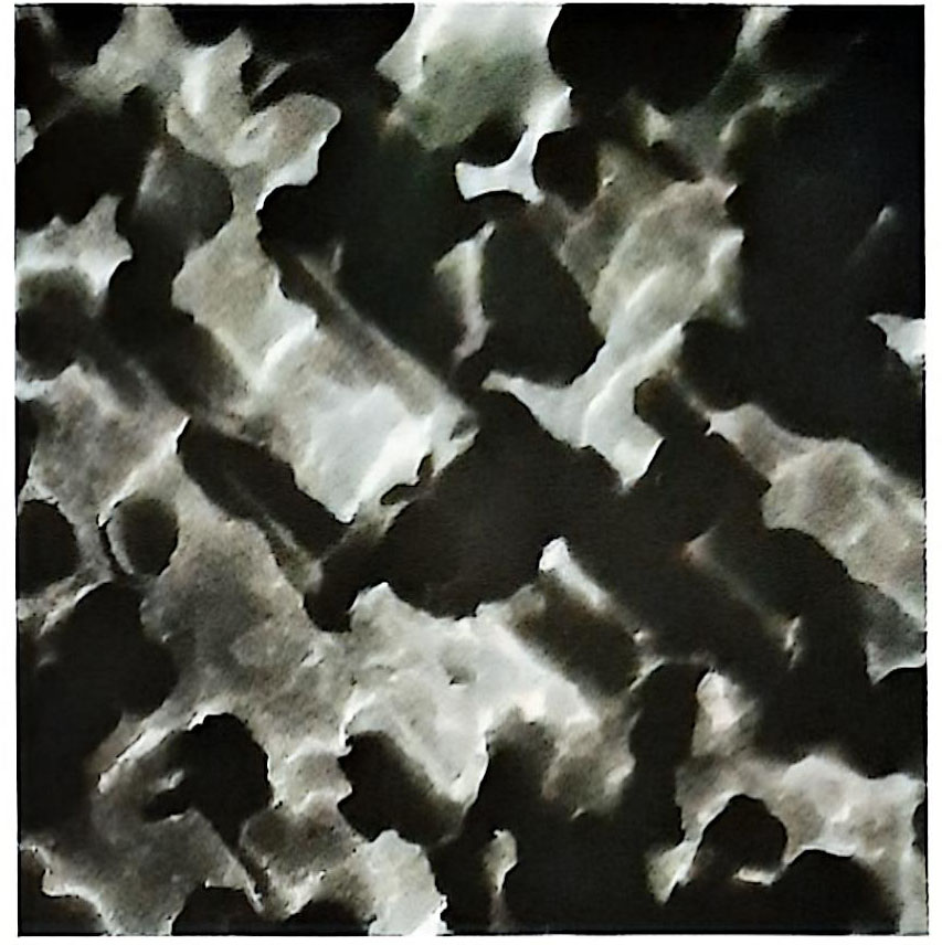
Figure 2 Microstructure of the anode aluminum foil after corrosion processing
The positive plate of the aluminum electrolytic capacitor is the anode foil, the dielectric is the insulating aluminum oxide on the anode foil, the real negative plate is the conductive liquid electrolyte, and the cathode aluminum foil is the lead-out electrode of the real negative electrolyte.
Since the surface area of the anode aluminum foil after corrosion processing is hundreds of times its geometric area, as shown in Figure 3, and the thickness of the aluminum oxide dielectric is also less than a micron. Therefore, the capacitor obtained has a huge plate area and a very close plate distance, so a very large capacitance can be obtained. The capacitance can generally reach 2700000µF/6.3V (produced by CDE) and 10000 µF/450V (produced by Jianghai Capacitor Factory), which is close to 3F; the rated voltage can cover the entire voltage range from low voltage 3V to high voltage 500V.
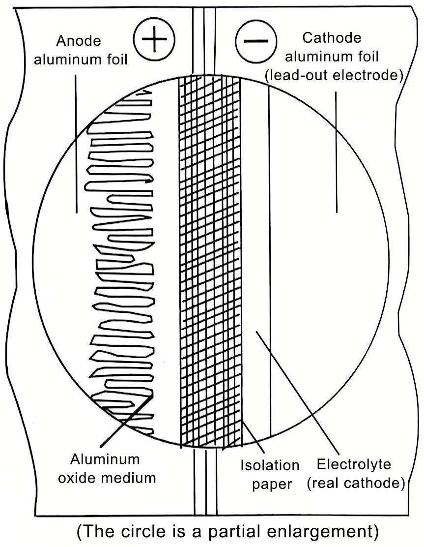
Figure 3 Schematic diagram of the structure of aluminum electrolytic capacitor
From the above description, it can be seen that ordinary capacitors have obvious positive and negative terminals, and are polar components that cannot be used in reverse polarity.
2.2 Manufacturing process
The manufacturing process the principle of aluminum electrolytic capacitors mainly consists of the following steps.
(1) Corrosion
The anode and cathode aluminum foils are composed of very pure and thin aluminum foils with a thickness of 0.02~0.1mm. In order to increase the panel area and capacitance, the foil can be corroded to form a very rough surface to increase the surface area, and the electrolyte can be used to achieve close contact with the very rough surface.
(2) Forming an aluminum oxide dielectric film through anodization
The dielectric of the aluminum electrolytic capacitor is covered on the anode foil. This dielectric is a thin layer of aluminum oxide, Al2O3, which is formed on the positive foil by electrochemical methods in a process called “anodization”. The process is as follows: the positive foil on the aluminum coil is passed through an electrolyte tank and a DC voltage is continuously applied to the tank to complete the formation process. The voltage is 135%~200% of the final capacitor rated voltage. Therefore, the dielectric thickness of aluminum electrolytic capacitors can be precisely controlled. Usually the thickness of the aluminum oxide is about 1.4~1.5nm per volt formed. For example, the positive foil of a 450V capacitor can be formed at a voltage greater than 600V, and the oxide thickness is 900nm, less than 1/100 of the diameter of a human hair.
Because microscopic parts may be blocked by aluminum oxide, anodization reduces the effective anode surface area. It is also possible to make full use of the microstructure of the low-voltage positive electrode through special corrosion modes through the selection of foils and etching processes. The cathode foil is not anodized to maintain its large surface area in close electrical contact with the electrolyte.
(3) Cutting
40~50cm After the wide aluminum foil roll is corroded and anodized, it is divided into many widths according to the length of the capacitor.
(4) Riveting and winding
The lead wires of the anode foil and cathode foil are riveted or welded to the anode foil and cathode foil. The anode foil and cathode box are interlaced between the isolation paper and wound into a capacitor core package (element) by a winding machine, and finally fixed in shape with tape.
(5) Impregnation
The capacitor core package is impregnated with electrolyte to saturate the paper isolation layer and immerse the corroded aluminum foil. This impregnation method requires the removal of gas in the core package, so the core package needs to be vacuum impregnated with electrolyte
(6) Sealing Sealing
The electrolyte is easy to volatilize at high temperatures, thereby reducing the effective area of the cathode. Therefore, in the principle of aluminum electrolytic capacitors, electrolytic capacitors need to be sealed. In the 1960s or earlier, in order to reduce costs and reduce the amount of aluminum used (the output of aluminum was not high at that time, and the aluminum in my country was mainly used to make aircraft), many commercial-grade electrolytic capacitors (called civilian products at that time) used wax paper barrels and were sealed with resin at both ends. Due to poor sealing, most of them failed after a few years of use (sometimes they completely failed in just one or two years, such as the steamboat sound of a tube radio-the self-excitation phenomenon caused by the harmful coupling caused by the high AC impedance of the power supply-is the electrolytic capacitor in the electrolytic capacitor. The remaining capacity after the liquid evaporates is insufficient, and the severe AC noise indicates that the filter electrolytic capacitor has completely failed. The working temperature is only 10-55℃. The current electrolytic capacitor core is sealed in a container. Most containers are made of aluminum. The container port is sealed with a rubber plug or rubber pad with good sealing and a resin plate and compressed (as shown in Figure 4) to effectively prevent the volatilization of the electrolyte. In order to prevent the explosion caused by the gas pressure generated by the electrolytic capacitor when it fails, electrolytic capacitors with a diameter of more than 8mm are equipped with a pressure release device. Usually, K, > and ✕-shaped indentations are engraved on the end face of the aluminum shell to cause the internal gas pressure of the electrolytic capacitor to expand and rupture before the rubber plug is opened.
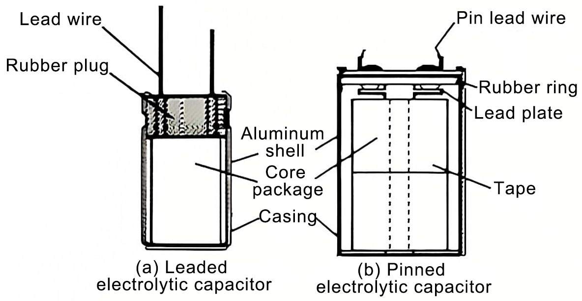
Figure 4 Schematic diagram of the structure of an aluminum electrolytic capacitor
(7) Aging
In the principle of aluminum electrolytic capacitors, the last step in the manufacture of electrolytic capacitors is aging, also known as empowerment. Its function is to repair the film damage of the aluminum oxide medium during the manufacturing process (especially the cutting process of the anode aluminum foil) by applying a forward voltage (similar to the anodizing process) to minimize the defects of the electrolytic capacitor. This is the process of applying a DC voltage greater than the rated voltage but less than the original anodizing voltage of the aluminum foil to the capacitor. The voltage is usually applied at the rated temperature of the capacitor, but it may also be applied at other temperatures or even room temperature. Through aging, the damage to the aluminum oxide dielectric of the electrolytic capacitor and the corrosion of the aluminum oxide dielectric by chloride ions can be repaired. For electrolytic capacitors that still fail to meet the performance (mainly leakage) after aging, they are considered unqualified and removed from the product, which can effectively reduce or eliminate early failures (factory damage). Of course, the current reaching the index is a sign that aging is complete.