1.Metallized Paper Dielectric Capacitor
Metallized paper capacitor is a dielectric capacitor made of metallized paper as the main material. Its electrode is not made of metal foil, but a very thin metal film is deposited on the capacitor by vacuum evaporation, as shown in Figure 1 (a). Its classification is the same as that of paper dielectric capacitors. The main characteristics of metallized paper capacitors are: self-healing effect, and the specific capacitance is larger than that of similar paper dielectric capacitors.
2.Composite Dielectric Capacitor
The dielectric of composite dielectric capacitor is made of different materials combined together. In capacitor manufacturing, the composite dielectrics that have been used include polar film and capacitor paper combination, non-polar film and capacitor paper combination, and polar film and non-polar film combination. The purpose of using the first two composite dielectrics is to improve the insulation strength of the capacitor, while the latter can reduce the capacitance temperature coefficient of the capacitor.
Polar films combined with capacitor paper are commonly used polyester films and polycarbonate films. The capacitor made of composite dielectric composed of polyester film and capacitor paper has good moisture resistance in addition to its small size. Compared with paper dielectric capacitors, composite dielectric capacitors have a large high temperature time constant and a longer life. Compared with film capacitors, composite dielectric capacitor have smaller losses and higher corona voltage at higher temperatures. Commonly used non-polar films combined with capacitor paper include polystyrene film and polypropylene film. Capacitor paper-polystyrene capacitors are easier to impregnate than polystyrene capacitors, and their insulation strength and heat resistance are improved, and the capacitance temperature coefficient is also improved. If the polystyrene film is replaced with polypropylene film, it can not only improve the breakdown voltage and heat resistance of the capacitor, but also reduce the cost.
3. Double-sided metallized paper-plastic film capacitor
Double-sided metallized paper-plastic film capacitor (double-sided metallized paper-plastic film capacitor) is a capacitor made by alternately stacking double-sided metallized paper and plastic film, winding them into a core, spraying metal on the ends, connecting the metal film electrodes on both sides of the capacitor paper, and welding the leads to seal the shell. Plastic film generally uses polyester, polypropylene or polycarbonate. Capacitor paper is purely used as a carrier of the regenerated electrode, and the plastic film is used as the medium of the capacitor, that is, only the plastic film is subjected to the effect of the electric field. In this way, the characteristics of low loss and high insulation strength of the plastic film will be fully utilized.
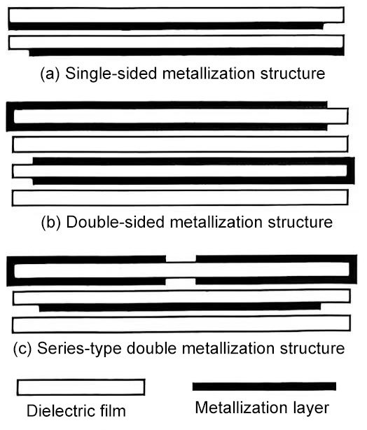
Figure 1 Bimetallized structure
This capacitor has strong self-healing ability and high voltage stability because the metal film is tightly attached to the surface of the paper. Compared with the metal film evaporated on the plastic film, the metal film evaporated on the paper has more reliable contact, and the short-term high temperature does not affect the shape of the metal film, so it can withstand a higher current load. Since the plastic film is not metallized, even if there are defects such as defects such as defects and pinholes on the plastic film, it will not cause a short circuit due to metallization, so the working strength is higher than that of the plastic film metallized capacitor. In addition, because the metal film is on the paper, during self-healing, the damage of the paper replaces the damage of part of the plastic film, thereby improving the re-breakdown strength and voltage stability of the plastic. Therefore, this capacitor has the characteristics of small size, low loss, high working voltage and large current load.
The bimetallized structure is shown in Figure 1(b). When a higher withstand voltage is required, the structure of Figure 1(c) can also be used. The electrodes are led out from the upper bimetallized layer. In this way, the bimetallized layer on the left and the bimetallized layer on the right form two capacitors with the single metallized layer on the bottom respectively. Then, through the connection of the single metallized layer on the bottom, the two bimetallized layers on the top form a capacitor in series, thereby obtaining twice the withstand voltage on the basis of a single insulating film.
4.Advantages of metallized capacitors
The obvious advantage of metallized capacitors over metal foil electrode capacitors is that they are self-healing. As a dielectric capacitor, when a metallized capacitor breaks down due to defects in the dielectric, an arc current will immediately be generated at the breakdown point, and the current density is concentrated at the center of the breakdown point. Since the metallized film is very thin (less than 0.1μm), the heat generated by the current is sufficient to melt and evaporate the metal near the breakdown point, forming a metal-free zone around the breakdown area, restoring insulation between the two electrodes of the capacitor, and restoring the normal operation of the capacitor.
Self-healing allows the full dielectric strength of the metallized capacitor to be utilized, while metal electrode capacitors must be designed with a certain safety margin to allow for any possible errors in the insulator.
Metallized capacitors have many advantages, which are particularly evident at large rated capacities.
Because of the metallized design, it can also be applied to some more complex capacitor designs, for example, multiple internal series connections for handling high DC voltages and high AC load coupling, as shown in Figure 1(c).
In capacitors that require high current pulses and high di/dt, a combination of metal foil, metal film and non-metal film can be used to enable capacitors to carry extremely high currents and self-heal.
5.Foil capacitors
Foil capacitors are the earliest form of wound capacitors. The metal foil used as the metal electrode is generally a cheap and ductile aluminum foil sandwiched between the insulating medium and wound. The electrode lead-out method is shown in Figure 2.
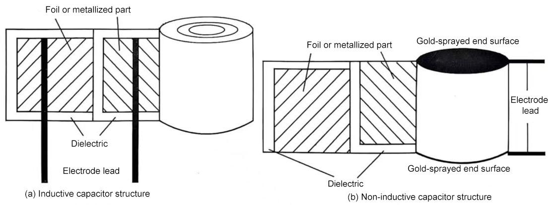
Figure 2 Structure of inductive and non-inductive capacitors
6.Inductive and non-inductive capacitors
The winding and electrode lead-out of the inductive capacitor are shown in Figure 2 (a). Obviously, this winding and electrode lead-out method will produce a relatively obvious inductance, especially from the short electrode part far away from the electrode lead-out to the electrode lead-out terminal, which will produce obvious parasitic inductance. Therefore, it is not suitable for high-frequency applications. Another disadvantage of inductive capacitors is that usually each electrode of inductive capacitors has only one electrode lead-out. Since the electrode is a foil or metallized film, the contact area with the lead-out wire is very small. If a large current is encountered, the contact between the lead-out wire and the electrode may be burned, and in severe cases, a breakdown point may be formed.
In order to minimize the parasitic inductance of the wound dielectric capacitor core, the electrode non-inductive lead-out method should be adopted as shown in Figure 2(b). From the figure, it can be seen that the two electrodes of the capacitor are each led out from one end face, eliminating the winding inductance of the electrode, so it is called a non-inductive capacitor. In fact, whether it is an inductive capacitor or a non-inductive capacitor, there is inductance as long as there is a spatial distance from the electrode to the lead-out terminal, but the parasitic inductance of the non-inductive capacitor is much smaller than that of the inductive capacitor. Similarly, the longer the length of the non-inductive capacitor, the greater its parasitic inductance (although this inductance is already very small). Therefore, in order to obtain a smaller parasitic inductance, a capacitor with a shorter size should be used.
Electrode lead-out of non-inductive capacitor: After the two-pole foil or metallized film of the non-inductive capacitor is led to both sides of the capacitor, the molten solder or other metal is sprayed to both ends of the capacitor core by compressed air, and the two-pole foil or metallized film is integrated with the metal sprayed on to form an electrode lead-out terminal. After being processed, these two electrode lead-out terminals can be used as electrode lead-out terminals of chip capacitors or as the cathode base of lead-type capacitors. This process is called metal spraying on the end face of the capacitor core, referred to as gold spraying. Depending on the different electrode materials, the materials for gold spraying are also different, mainly lead-tin alloy, lead-zinc alloy, aluminum, copper, etc.