Discrimination of Electrolytic Capacitor Polarity
The capacitance is deviated. Generally, the polarity will be marked with a symbol on the capacitor. Generally, the negative electrode is marked as “-” and the opposite is the positive electrode. The accuracy level of the capacitor corresponds to the allowable error. Generally I, II, and III are commonly used for capacitors. Electrolytic capacitors use IV, V, and VI levels to indicate capacity accuracy, which is selected according to the application.
The capacitance of a capacitor is numerically equal to the ratio of the amount of charge on one conductive plate to the voltage between the two plates. In circuit diagrams, the letter C is usually used to denote capacitive elements. The capacitance value of an electrolytic capacitor depends on the impedance presented when working under AC voltage. The capacitance value will change as the working frequency, temperature, voltage and measurement method change. The unit of electric capacity is F (French).
Extended information:
Capacitor capacity identification:
1. Direct marking method: Mark directly with numbers and unit symbols. Some capacitors use “R” to indicate a decimal point, such as R56 for 0.56 microfarads.
2. Text symbol method: Use a regular combination of numbers and text symbols to express capacity. For example, p10 means 0.1pF, 1p0 means 1pF, 6P8 means 6.8pF, and 2u2 means 2.2uF.
3. Color code method: use color circle or color dot to indicate the main parameters of the capacitor. The color code method of the capacitor is the same as the resistance.
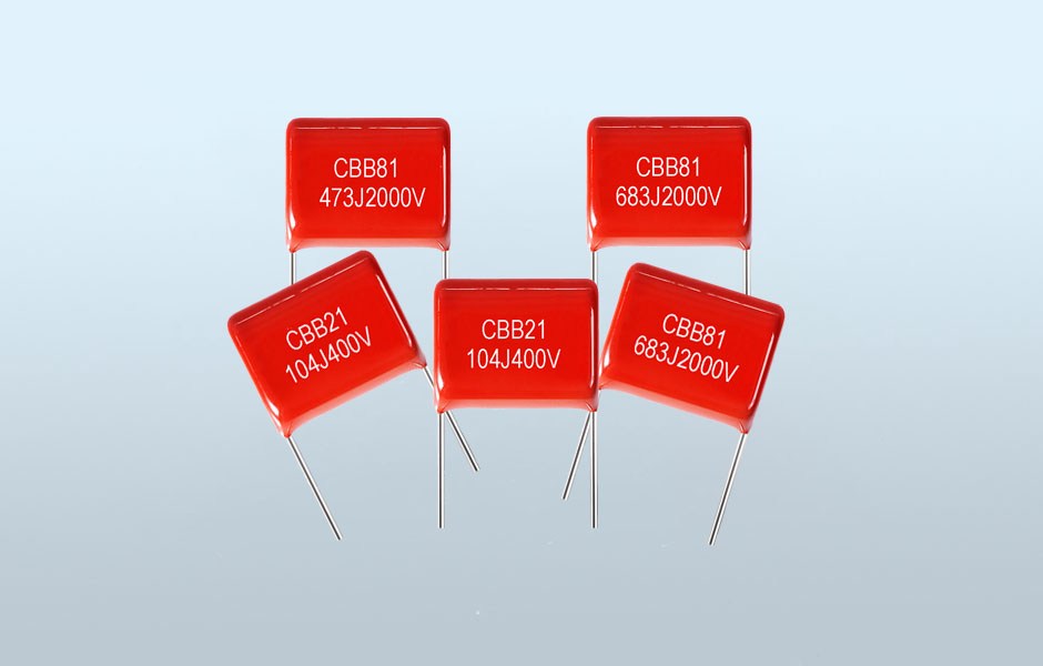
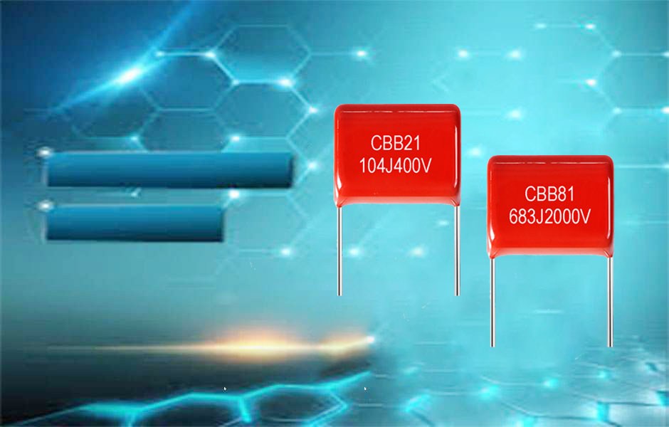
4. Mathematical notation: Mathematical notation is generally three digits, the first and second digits are significant digits, and the third digit is a multiple.
Discrimination of Electrolytic Capacitor Polarity
