1 DC filter protection configuration principles and characteristics
1.1 Relationship between DC filter protection and DC system protection
DC system protection adopts zoning configuration, which is divided into six major areas (converter protection area, DC switch field protection area, neutral bus protection area, grounding electrode lead and grounding electrode protection area, converter station AC switch field protection area, DC line protection area). Among them, DC filter protection is located in the DC switch field protection area. DC filter capacitor protection is part of DC system protection to ensure the stable operation of the system.
1.2 Configuration principles of DC filter protection
The configuration principles of DC filter protection are the same as those of DC system protection. They are derived from the configuration principles of AC system protection and have their own characteristics, mainly in the following aspects:
(1) Reliability. The protection device is a fully redundant “two-out-of-two” configuration. Each set of redundant configuration protection is exactly the same and has its own independent hardware equipment, including dedicated power supply, host, input circuit, output circuit and DC protection full function software, which avoids the main equipment or system shutdown caused by the failure of the protection device itself.
(2) Sensitivity. DC filter protection, like AC protection, has high sensitivity. At the same time, the protection configuration should be able to detect all possible operating conditions in the area that may cause the equipment to operate in a dangerous manner.
(3) Selectivity. The DC filter protection action is selective and is determined by the DC system protection zone configuration. Each area or device has at least one main protection with strong selectivity, which is convenient for fault identification. When a fault occurs in this area, it will not lead to an expansion of the scope of fault removal.
(4) Modifiability. The DC filter protection function is the same as other DC protection. Its parameters should be easy to modify. The protection configuration should take into account that the device test and maintenance will not affect the operation of the protected system.
1.3 Characteristics of DC filter protection
(1) DC disconnector is used to cut off the fault current. When a minor fault occurs in the DC filter and the fault current is small, the DC disconnector cuts off the small fault current. DC filter capacitor protection also plays an important role in this process to ensure that the capacitor is not affected by overload.
(2) Closely related to the DC control system. The strategy of DC filter protection action is to alarm or trip the DC filter disconnector for minor faults, and directly lock the converter by the DC control system for serious faults.
(3) Dual configuration. In order to prevent the DC filter protection device from failing and causing a reduction in operating reliability, the protection device adopts a redundant configuration. The redundancy of the DC filter protection is used to improve the reliability of the protection device itself, and ultimately achieve the purpose of improving the reliability of the entire system. The DC filter capacitor protection also plays a key role in the redundant configuration.
2 DC filter differential protection
The following introduces the basic content of DC filter device protection. This article selects a mature converter station that has been in operation in China for introduction. The protection-related configurations and settings for different DC converter stations may be slightly different. When reading, readers will not be affected by the learning and mastering of basic information such as the DC filter protection principle and criteria.
2.1 Purpose and scope of protection
The purpose of this protection is to detect ground faults in the DC filter protection area. The protection scope includes the entire DC filter, and also involves DC filter capacitor protection to ensure that the filter and capacitor are effectively protected in the event of a ground fault.
2.2 Protection principle
Measure the DC currents on the high and low voltage sides of the DC filter. In normal operation, these currents are balanced. When a ground fault occurs in the DC filter, DC shunts will occur, resulting in an imbalance in the DC currents on the high and low voltage sides. This protection detects the grounding fault of the DC filter by detecting the differential current, and shuts down the DC filter when a grounding fault occurs in the DC filter. The protection of the DC filter capacitor also plays a key role in this process. Through effective capacitor protection, the fault extension is avoided and the safe operation of the system is ensured. Its protection principle is shown in Figure 1.
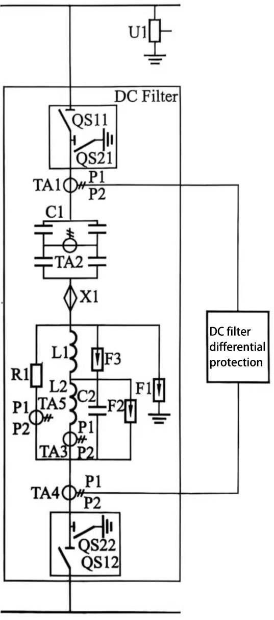
Figure 1 Schematic diagram of DC filter differential protection
2.3 Judgment criteria and setting principles
This differential protection is divided into three sections according to various possible faults.
(1) DC filter differential section I. |ITA1−ITA4|>8A+20%×ITA1,Delay 150ms, alarm.
(2) DC filter differential section II. |ITA1−ITA4|>40A+50%×ITA1, delay 200ms, trip the DC filter when the current on the high-voltage side of the DC filter is lower than 50A, and lock the converter valve when the current on the high-voltage side of the DC filter is higher than 50A.
(3) DC filter differential section II.∣ITA1−ITA4∣>150A+20%×ITA1, delay 10ms, lock the converter.
2.4 Protection action sequence
(1) Alarm.
(2) Trip the high and low voltage side disconnector of the DC filter.
(3) Lock the converter valve.
3. Unbalance protection of the high voltage capacitor tower C1 of the DC filter
3.1 Purpose and scope of protection
The purpose of this protection is to detect the fault of the high voltage capacitor group of the DC filter.
The protection scope is the high voltage capacitor tower (group) of the DC filter, and also covers the protection of the DC filter capacitor to ensure that the fault of the capacitor tower can be identified and handled in time.
3.2 Protection principle
Detect the current of the DC filter ITA2 and ITA4. If ITA2/ITA4 exceeds the set value, the protection is activated. The unbalance protection adopts the ratio unbalance design principle (some converter station unbalance protection directly adopts the protection principle that a certain characteristic frequency current is greater than a certain set value, such as the Longquan converter station in Yichang, Hubei, and the Zhengping converter station in Changzhou, Jiangsu). The protection principle is shown in Figure 2.
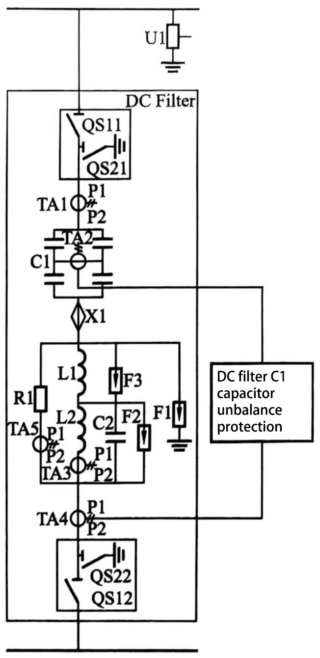
Figure 2 Schematic diagram of DC filter ratio unbalance protection
3.3 Judgment criteria and setting principles
ITA2/ITA4>Δ, the setting of the fixed value is determined according to the unbalanced current and the filter current.
Typical fixed values:
ITA2/ITA4>Δ1, t=120s, alarm.
ITA2/ITA4>Δ2, t=2h, when the current on the high-voltage side of the DC filter is lower than 50A, the DC filter is tripped, and when the current on the high-voltage side of the DC filter is higher than 50A, the converter valve is locked.
ITA2/ITA4>Δ3, t=10ms, when the current on the high-voltage side of the DC filter is lower than 50A, the DC filter is tripped, and when the current on the high-voltage side of the DC filter is higher than 50A, the converter valve is locked.
3.4 Protection action sequence
(1) Alarm.
(2) Trip the high- and low-voltage side isolation switches of the DC filter.
(3) Lock the converter valve.
4.DC filter overload protection
4.1 Purpose of protection
The purpose of this protection is to detect overload of the DC filter and avoid overstress of the DC filter. Through effective DC filter capacitor protection, capacitor damage caused by overload can be avoided.
4.2 Protection principle and strategy
Detect the harmonic current of the inductor L1, L2 and resistor R in the DC filter. If it exceeds the set value, the protection will be activated. The protection action delay should be able to avoid the influence of transient overload to avoid false operation. The protection principle is shown in Figure 3.
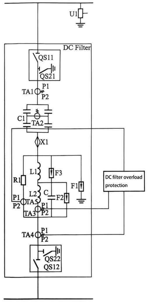
Figure 3 Schematic diagram of DC filter overload protection
Protection coordination: The setting of the set value takes into account the thermal tolerance of the filter device, especially in the protection of DC filter capacitors, to ensure that the capacitor will not be subjected to excessive thermal stress under overload conditions.
4.3 Judgment criteria and set value setting principles
According to the overload situation, it is divided into 3 sections:
(1) Overload alarm section. When the overload judgment of reactor L1 is ITA4−ITA5>Δ and the overload judgment of reactor L2 is ITA3>Δ or the overload judgment of resistor R1 is ITA5>Δ, the delay is 600ms and the alarm is triggered.
(2) Overload protection stage I. When the overload of reactor L1 is ITA4−ITA5>Δ and the overload of reactor L2 is ITA3>Δ or the overload of resistor R1 is ITA5>Δ, the delay is 30s. When the current on the high-voltage side of the DC filter is lower than 50A, the DC filter is tripped, and when the current on the high-voltage side of the DC filter is higher than 50A, the converter valve is locked.
(3) Overload protection stage II. When the overload of reactor L1 is ITA4−ITA5>Δ and the overload of reactor L2 is ITA3>Δ, the delay is 500ms. Resistor R1 overload ITA5>Δ, delay 100ms, trip the DC filter when the current on the high-voltage side of the DC filter is lower than 50A, and lock the converter valve when the current on the high-voltage side of the DC filter is higher than 50A.
4.4 Protection action sequence
(1) Alarm.
(2) Trip the high- and low-voltage side disconnectors of the DC filter.
(3) Lock the converter valve.
5 DC filter harmonic monitoring protection (when both bipolar DC filters are in operation)
5.1 Purpose and scope of protection
The purpose of this protection is to detect the detuning of the DC filter.
The protection scope is to protect the two-pole DC filter when both bipolar DC filters are in operation; when non-bipolar DC filters are in operation, the protection is locked.
5.2 Protection principle
When both bipolar DC filters are in operation, detect the 12th harmonic current difference of the same type of bipolar DC filters ITA4>Δ. If it exceeds the set value, alarm. When both bipolar DC filters are not in operation, this protection is exited. This protection can also be coordinated with the DC filter capacitor protection to ensure that the filter and capacitor can operate stably under harmonic load.
5.3 Protection criterion
|ITA4_12th||-|ITA4_12th_LP||>Δ, ITA4_12th is the 600Hz component of the low-voltage neutral line current of the DC filter of this pole, and ITA4_12th_OP is the 600Hz component of the low-voltage neutral line current of the opposite pole filter.
5.4 Protection action result
Alarm.