1.Capacitor CurrentSurge Characteristics and Limiting Factors
Capacitors are subject to dv/dt and current surges in some applications. Theoretically, capacitors can withstand unlimited current surges. Furthermore, when used as high-frequency rectifier and filter capacitors, despite low ripple voltage, they can still flow high currents due to the relatively high frequency. However, to achieve compact size and low cost, practical capacitors must use electrodes as thin as possible, such as metallized electrodes. These electrodes have very small conductive areas, The capacitor current that can naturally withstand It is limited. Therefore, practical capacitors have current limitations (RMS and peak current).
So, which external circuit operating conditions will be constrained by the capacitor’s current limit? This is one of the key technical parameters XUANSN considers when designing high-performance capacitor products.
2 Capacitor current generation and film capacitor dv/dt tolerance
dv/dt seems to be a parameter related to voltage. What is its relationship with capacitors? From the most basic relationship between capacitor voltage and current:
![]() (1)
(1)
Differentiating both sides yields ![]()
After sorting, we get
![]() (2)
(2)
It is obvious that the capacitor current is generated by the change in capacitor terminal voltage. This current is proportional to the capacitance and the rate of change of capacitor terminal voltage over time. The larger the dv/dt, the larger the capacitor current.
The dv/dt of the capacitor terminal voltage varies in different applications. For example, the maximum value of dv/dt applied to 50Hz/380V AC is 0.027V/μs. This dv/dt value is very small for capacitors and can be easily met. In the DC state, dv/dt is zero, and there is no dv/dt problem. Capacitors used as snubber capacitors for switching transistors (especially IGBTs, which serve as the main switches in high-power switching power supplies, inverters, welding machines, and other high-power electronic circuits) inevitably face dυ/dt limitations. A 0.47μF capacitor subjected to a voltage rise rate of 500V/μs will have a peak current of 235A. Under these application conditions, the capacitor’s dυ/dt, or peak current withstand capability, is a crucial parameter. General-purpose capacitors generally do not require specification of their peak current withstand capability or dυ/dt value. The actual dυ/dt withstand value for these capacitors is generally between 1 and 50V/μs. This value is significantly greater than the dυ/dt value at 50Hz/380V, so the capacitor’s dυ/dt value is generally not a consideration for applications below 1kHz. For the same capacitance, the dυ/dt value of a low-voltage capacitor is generally lower than that of a high-voltage capacitor.
In power electronics, when MOSFETs are used as switches, a snubber capacitor is often required to divert the MOSFET’s current to the snubber capacitor when the MOSFET turns off. The voltage must rise to 300-600V within 0.1-0.5μs. The capacitor will withstand voltage surges of 1000-6000V/μs. For a 1000pF capacitor, the peak capacitor current flowing through will reach 1-6A. For a 10nF capacitor, this peak current will reach 10-60A. These operating conditions require a capacitor with a high dυ/dt withstand capability, necessitating the use of a dedicated snubber capacitor. Table 1 shows the dυ/dt values that CDE snubber capacitors can withstand.
Table 1 shows the dv/dt values that CD snubber capacitors can withstand.
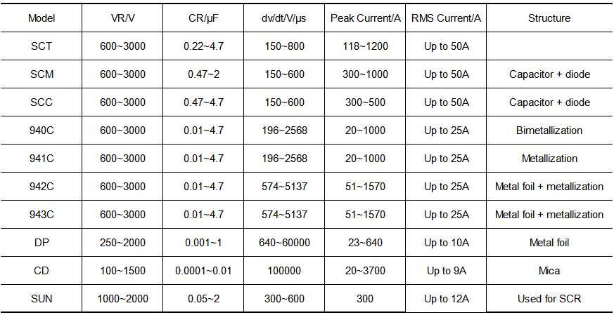
Table 1 shows the dv/dt and peak current withstand capabilities of metal electrode capacitors compared to metal film capacitors. Because the current caused by dv/dt, while peak current is high, its duration is short and the duty cycle is low, the actual effective current flowing through the capacitor is very small compared to the peak current. In this state, the peak current is the maximum impact on the capacitor.
In terms of dielectric material, snubber capacitors are almost exclusively made of polypropylene, with a very small number of mica materials (which have extremely high dv/dt). SCR snubber capacitors, on the other hand, use paper dielectrics. Therefore, in applications with relatively high currents, such as pillow capacitors for color TVs and resonant/starting capacitors for electronic ballasts, users almost invariably choose “CBB capacitors” (the national standard code for polypropylene capacitors).
The disadvantage of domestic high dv/dt film capacitors is that the product catalogs of domestic film capacitor manufacturers almost invariably lack information on dv/dt values or pulse current ratings, nor do they include data on the effective current they can withstand, let alone ESR. They simply state that they can withstand high pulse currents, leaving users confused when selecting a capacitor, as they have no idea what specific data to refer to.
3 Effective current carrying capacity of film capacitors
In high-frequency rectification and filtering applications, the voltage change seen across the filter capacitor is not large, that is, dv/dt is not large. Even so, if improperly applied, the capacitor will heat up or even be damaged. In this case, the effective current of flowing through the capacitor is the main cause of capacitor heating, that is,
![]() (3)
(3)
When a capacitor with an ESR of 0.1Ω flows through an effective current of 5A, the power consumption is 2.5W; when the ESR is reduced to 0.01Ω, its power consumption will be reduced to 0.25W; if it is 0.005Ω, the power consumption is as low as 0.125W. For capacitors with poor heat dissipation performance, having the lowest possible ESR will be beneficial to the operation of the capacitor. In order to achieve the lowest possible ESR, the cross-sectional area of the lead electrode of the capacitor dedicated to high-frequency rectification and filtering is relatively large.
4.Requirements forResonance and Phase Compensation Capacitors in Thyristor Medium-Frequency Power Supplies
In thyristor medium-frequency power supplies, thyristor commutation requires load resonance to generate a reverse voltage across the thyristors. Since the actual load is purely inductive, a capacitor is required to compensate for this in a parallel resonant state. This capacitor serves as the phase compensation capacitor. The output power of thyristor medium-frequency power supplies is very high (at least 100kW). For example, one medium-frequency power supply in a certain factory has an output power of 2MW. The output current of the thyristor inverter is nearly 400A, and the current in the resonant tank (approximately the current in the phase compensation capacitor) will reach 3000-5000A.
Even with an ESR of only 0.1mΩ, the losses are still as high as 900-2500W. Therefore, water-cooled capacitors are often used for reliable heat dissipation. XUANSN has extensive experience in producing water-cooled capacitors for medium-frequency power supplies. These products are widely used in resonant, compensation, and filtering systems, meeting the demands of high-current, high-power density industrial applications.
The key parameters of resonant and phase-compensation capacitors in thyristor medium-frequency power supplies include rated voltage, rated capacity, fixed frequency, and cooling method. The first three parameters provide the capacitor current can withstand. For example, the “RFM0.75-360-1S” medium-frequency electrothermal capacitor produced by Jiufang Herong in my country has a rated voltage of 0.75kV, a rated capacity of 720kvar, and a rated frequency of 1kHz.
Comparable XUANSN products offer superior current handling and thermal stability under similar conditions, providing reliable support for high-power electronic systems.