1 Voltage and Aluminum Electrolytic Capacitors
The voltage indicators of aluminum electrolytic capacitor mainly include: rated DC voltage, rated surge voltage, transient overvoltage and reverse voltage, etc., which will be introduced one by one below.
(1) Rated DC voltage
The rated DC voltage VR is the continuous working voltage allowed by the capacitor within the rated temperature range. It includes the DC voltage and pulsating voltage or continuous pulse voltage between the two electrodes of the capacitor. Usually, the rated voltage of aluminum electrolytic capacitors is indicated on the surface of the capacitor. Usually, the rated voltage ≤100V is a “low voltage” aluminum electrolytic capacitor, while the rated voltage ≥150V is a “high voltage” aluminum electrolytic capacitor.
(2) Working voltage
The working voltage Vop is the voltage allowed by the capacitor to work continuously within the rated temperature range. Within the entire working temperature range, the capacitor can work continuously at the full rated voltage (including AC superimposed voltage) or at any voltage value between 0V and the rated voltage. For a short time, the capacitor can also withstand a reverse voltage of 1.5V.
(3) Reverse voltage
The operating voltage Vop is the voltage that the capacitor is allowed to operate continuously within the rated temperature range. Within the entire operating temperature range, the capacitor can operate continuously at the full rated voltage (including AC superimposed voltage) or at any voltage between 0V and the rated voltage. In a short period of time, the capacitor can also withstand a reverse voltage of 1.5V.
(4) Rated surge voltage
The rated surge voltage Vs is the short-term voltage value that the aluminum electrolytic capacitor can withstand. The test conditions are: the capacitor operating temperature is 25℃, not more than 30s, and the interval between two times is not less than 5min. The relationship between surge voltage and rated voltage specified in IEC 384-4 is as follows:
When V<315V, Vs=1.15VR(1)
When V>315V, Vs=1.10VR(2)
(5) Surge voltage measurement
The specific test method for the rated surge voltage Vs of a capacitor is: At normal ambient temperature, aluminum electrolytic capacitors with a capacitance of less than 2500µF can be connected in series with a 1000Ω±10% resistor to limit the initial charging current. For capacitors with a capacitance of 2500µF or higher, the value of the current limiting resistor in series is based on the following: the product of the resistance value of the series resistor and the capacitance of the capacitor under test (time constant) is equal to 2500000Ω·µF. If the capacitor under test is 10000µF, the series resistor is 250Ω, and so on. During the period of 30s on and 270s off, each capacitor is discharged through a charging resistor or equivalent resistor. Repeat the cycle for 120h. The requirements for passing the test are that the DC leakage current (DCL), ESR and dissipation factor (DF) values should not change before and after the test, and there should be no mechanical damage or electrolyte leakage. Through this test condition, it can be seen that the time constant of the aluminum electrolytic capacitor and the series resistor is 2.5s, and 30s is 12 time constants. Such a long connection time can allow the aluminum electrolytic capacitors to charge to the surge voltage value. A total of 1440 shocks were made in 120h. If the quality is not up to standard, it will definitely fail after so many shocks.
(6) Transient overvoltage
The maximum overvoltage that aluminum electrolytic capacitors can generally withstand instantly. Overvoltage applications exceeding 50V, which is greater than the surge voltage rating of the capacitor, can cause large leakage current and constant voltage state, much like the reverse characteristics of a Zener diode. If the electrolytic cannot withstand this transient overvoltage, the capacitor may fail, but if it can withstand it, this state will not last too long, because the pressure generated by the hydrogen generated by the capacitor will cause the irreversible pressure relief device to operate, causing the aluminum electrolytic capacitor to fail. In special applications (such as those that need to withstand the impulse voltage of lightning strikes), special designs can be used, such as connecting transient voltage suppression diodes or high-performance varistors in parallel at both ends of aluminum electrolytic capacitors to successfully achieve instantaneous overvoltage protection.
(7) AC superposition, ripple voltage
Not only DC voltage can be applied between the two ends of aluminum electrolytic capacitors, but also AC superposition voltage or ripple voltage can be applied, but the following conditions must be met: ① The sum of the DC voltage and the AC superposition voltage and ripple voltage does not exceed the rated voltage, and reverse polarity does not occur; ② The current does not exceed the rated ripple current.
Figure 1 shows the relationship between the rated voltage VR, surge voltage VS, anodization voltage (breakdown voltage) VF, and leakage current of aluminum electrolytic capacitors. It can be seen from the figure that VF>VS>VR, and the leakage current increases with the increase of the terminal voltage of the electrolytic capacitor. When the terminal voltage exceeds the rated voltage and approaches the surge voltage, the rate of increase of the leakage current increases with the increase of the voltage. When the terminal voltage approaches the breakdown voltage, the leakage current will increase sharply and finally become a voltage characteristic similar to avalanche breakdown. The rated voltage of an aluminum electrolytic capacitors can be measured by the characteristic that the leakage current of the aluminum electrolytic capacitor increases significantly after the capacitor terminal voltage approaches the surge voltage.
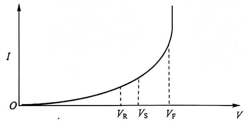
Figure 1 Relationship between voltage and current of an aluminum electrolytic capacitor
2 Capacitance
The capacitance indicators of aluminum electrolytic capacitors mainly include: rated capacitance, electrostatic capacitance, temperature characteristics of capacitance, frequency characteristics of capacitance and tolerance range of capacitance.
(1) Rated capacitance
The rated capacitance is the nominal capacitance, defined at 120Hz and 25℃. The rated capacitance, that is, the nominal capacitance of the single capacitance, is mostly the preferred value of the E3 series, namely: 1.0, 2.2, 3.3, 4.7.6.8. A few also use the preferred values of the E6 series, namely: 1.0, 1.5, 2.2, 2.7, 3.3, 3.9, 4.7, 5.6, 8.2.
Electrostatic capacitance, also known as DC capacitance, is measured when a DC voltage is applied to the capacitor. At room temperature, the capacitance is slightly larger than that of AC and has superior stability characteristics.
(2) Capacitance measurement
The capacitance of a capacitor can be measured by testing its AC impedance or the amount of electricity it can hold under a DC voltage. The results of the two methods are slightly different. Generally speaking, the capacitance value (DC capacitance) measured by the DC voltage test method is slightly higher than the capacitance value (AC capacitance) measured by the AC current method.
In order to be consistent with the most common application conditions (such as rectification and filtering or DC isolation coupling), the AC capacitance of aluminum electrolytic capacitors is the most common test frequency, which is generally twice the frequency of 50Hz or 60Hz AC. IEC384-1 and IEC384-4 give a frequency of 100Hz or 120Hz, which is measured by the special test method given in IEC384-1 and IEC384-4.
An AC voltage detector of 0.5V or less (which will not cause reverse breakdown of the aluminum electrolytic capacitor) can be applied to the aluminum electrolytic capacitor. The current capacitance can be determined based on the relationship between the capacitive reactance and the capacitance at a fixed frequency and the relationship between the capacitive reactance and the voltage current C=I/(2πf·V). The change of AC capacitance with temperature may be greater than 10%, and it also decreases with increasing frequency. Therefore, IEC384-1 and IEC384-4 give the basic test conditions at a frequency of 100Hz or 120Hz and a temperature of 20℃. The test method for testing the capacitance of general capacitors can also be used. Using the bridge circuit used for testing capacitors, a maximum 1Vrms AC signal voltage is applied to the power supply side. This AC signal voltage is a 120Hz sinusoidal voltage without DC division and high-order harmonics and sub-harmonics. Although the peak value of the power supply voltage is close to 1.5V, the peak voltage applied to the aluminum electrolytic capacitor will be lower than 1V through the voltage division of the bridge circuit, which will not cause damage to the aluminum electrolytic capacitor. Generally speaking, aluminum electrolytic capacitors are mostly used for filtering and DC isolation coupling after rectification. The value and accuracy of the capacitance are not high, and the capacitance tolerance (accuracy) of ±20% can meet the requirements well.
In some applications (such as discharge circuits and timing circuits), DC capacitance will play a decisive role. This requires measuring the DC capacitor. Usually, the charging/discharging method can be used. According to the relationship between capacitance and charge, voltage and the relationship between charge and current, the constant current charging/discharging method [C=(I·t)/△VC] is used to obtain the capacitance C by detecting L. Therefore, when accurate DC capacitance is required, it is best not to use aluminum electrolytic capacitors. Even if it is used, large and small capacitors should be connected in parallel to obtain a more accurate capacitance.
However, there are some exceptions where DC capacitance needs to be determined. The IEC publisher did not give any relevant instructions. Therefore, an independent DIN standard was determined. This standard–DIN41328–Part 4, describes the test method for one-time, non-cyclic charging/discharging capacitors.
(3) Capacitance temperature characteristics
Capacitance changes with temperature. The change itself is determined by the rated voltage and capacitor size. The capacitance increases by less than 10% from 25℃ to the high temperature limit. For the lowest rated temperature of -40℃, the capacitance of low-voltage capacitors typically decreases by 20%, and the capacitance of high-voltage capacitors decreases to 40%. Most of them decrease by less than 10% at -40℃ and less than 20% at -55℃. The relationship between capacitance and temperature of aluminum electrolytic capacitors with different rated voltages is shown in Figure 2. As can be seen from the figure, usually, the characteristic curve is steeper at low rated voltages, which is usually the result of rougher corrosion (deep corrosion) to increase the surface area of the anode. Of course, special electrolytes (the viscosity of the electrolyte changes less with temperature) can also be used to obtain a smaller capacitance that changes with temperature, so that the capacitor can operate in a large range below 0℃ without much capacitance change, which is meaningful in special applications.
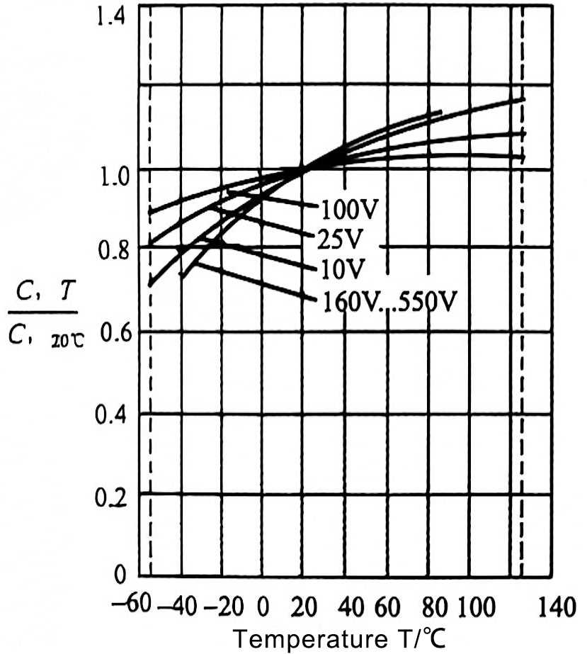
Figure 2 Relationship between capacitance and temperature of electrolytic capacitors
(4) Relationship between capacitance and frequency
The effective capacitance decreases with increasing frequency. A common view is that this is caused by dielectric absorption and loss factor. This concept is undoubtedly correct for film capacitors with dielectric loss as the main loss, but the loss in aluminum electrolytic capacitors is the loss caused by the electrolyte’s own resistance as the electrode. The frequency characteristics of aluminum oxide will never be that bad! Therefore, the characteristic that the capacitance of aluminum electrolytic capacitors decreases with the increase of frequency should not be a problem of dielectric loss. So where is the problem? The author of this book believes that; because aluminum electrolytic capacitors corrode the anode/cathode aluminum foil very rough to increase the electrode surface area, the cathode of the electrolyte corresponds to the deep part of the rough anode electrode. Because the electrolyte has a high resistivity, the capacitance deep in the rough anode electrode to the lead end has actually become an RC circuit. As the frequency increases, the effect of this sub-capacitor becomes weaker and weaker, and the equivalent capacitance becomes smaller and smaller. This is the real reason why the capacitance of aluminum electrolytic capacitors decreases with the increase of frequency. The similar equivalent circuit of aluminum electrolytic capacitors will be studied and analyzed in detail in Section 4.7. Figure 3 shows the relationship between the capacitance and frequency of aluminum electrolytic capacitors.
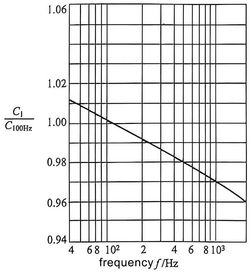
Figure 3 Relationship between capacitance and frequency of aluminum electrolytic capacitors
3 Leakage current
(5) Capacitance tolerance
Capacitance tolerance is the ratio of the difference between the minimum or maximum capacitance allowed and the rated capacitance to the rated capacitance, usually expressed as a percentage (△C/C). Typical capacitance tolerances are ±20%-10%+50% and -10%+75%. The tolerance of high-voltage capacitors can be made relatively small. For example, for capacitors greater than 150V, the general tolerance can be less than ±10%. Capacitance changes with temperature and frequency, and usually this change should also be within the capacitance tolerance range. Usually this change itself is also affected by the rated voltage and capacitance size of the capacitor.
Due to the special nature of the aluminum oxide dielectric as an insulating layer, the aluminum oxide dielectric is corroded by chloride ions in the electrolyte and produces defects, which leads to leakage current. This needs to be repaired by applying a DC voltage (anodic oxidation). Therefore, even if the DC voltage has been applied for a long time, a small repair current will still flow. This current is called leakage current. Low leakage current means that there are very few chloride ions in the electrolyte, and a good repair result can be obtained. It also shows that the aluminum oxide dielectric as an insulating layer is good. After applying voltage on the electrodes of the aluminum electrolytic capacitor, the iron and copper ions in the electrolyte will generate a galvanic effect current, which requires more charge to consume. This is why some aluminum electrolytic capacitors take a long time to reduce the “leakage current” to the normal value after power is applied.
(1) Leakage current measurement method
The test method and test conditions for leakage current of aluminum electrolytic capacitors are: at 25℃, the capacitor under test is connected in series with a 1000Ω protective resistor and connected to the rated voltage, and the leakage current is measured. After applying voltage for 5 minutes, the leakage current does not exceed the maximum value in the manual, which is qualified. Small-capacity aluminum electrolytic capacitors can use 1min test results, while large-capacity aluminum electrolytic capacitors will require longer test time. Figure 4 (a) shows the relationship between the current and time of an aluminum electrolytic capacitors connected to a DC voltage after a series resistor. From the characteristic curve, it can be seen that the current will infinitely approach the final leakage current value – the current value required to repair the aluminum oxide dielectric.
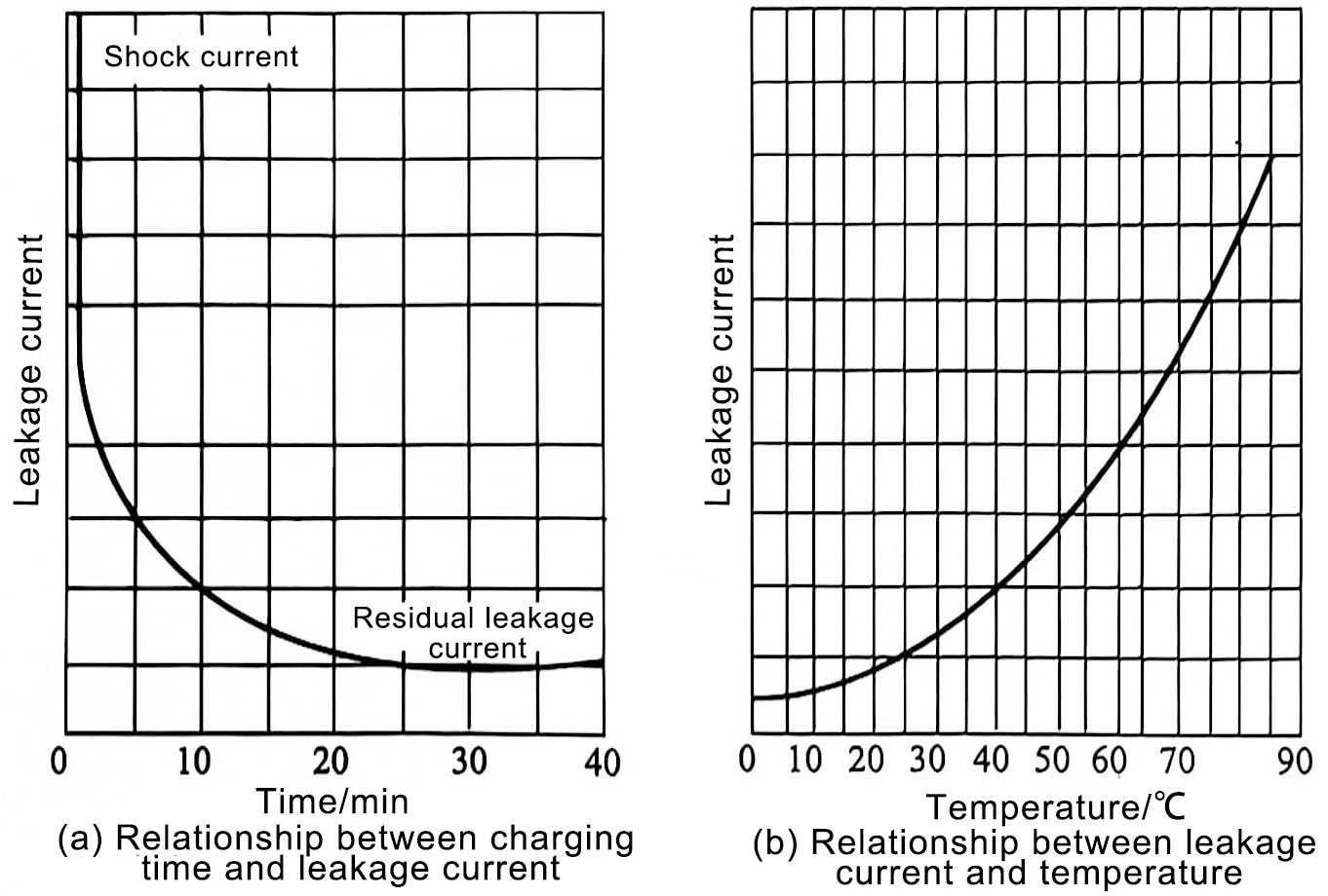
Figure 4 Relationship between leakage current and temperature of aluminum electrolytic capacitors
The leakage current of an aluminum electrolytic capacitor can be calculated. For example, the I1kop of an EPCOS aluminum electrolytic capacitors can be calculated by the following formula:
LL grade
![]()
GP grade
![]()
0.001μA.C ·V+3μAIikop =μF·V
Where, I1kop, Cr, and VR are the operating leakage current, rated capacitance, and rated voltage, respectively. This result is obtained at the rated voltage VR at 20℃.
It should be noted that when aluminum electrolytic capacitors are stored for a long time without voltage and without any application, the chloride ions in the electrolyte will cause the greatest damage to the aluminum oxide dielectric film, especially when stored under high temperature conditions. In this case, no leakage current flows from the oxide layer to the anode, and the oxide layer cannot be regenerated. As a result, when voltage is applied after extended storage, a leakage current higher than the normal value will be generated. However, as the oxide layer is regenerated during use, the leakage current will gradually decrease to the normal value. At the same time, the primary battery effect of iron and copper ions will gradually recover, which means that the leakage current of aluminum electrolytic capacitors will require a long period of applied voltage to recover. This process is called aging or empowerment. It is usually best to empower aluminum electrolytic capacitors before using them.
DC leakage current is the DC current flowing through the capacitor when the rated voltage is applied. The leakage current value is related to the applied voltage, charging time, and capacitor temperature.
Under no voltage conditions, aluminum electrolytic capacitors from domestic manufacturers can be stored for at least 1 year, and aluminum electrolytic capacitors from well-known foreign manufacturers can be stored for at least 2 years. A well-sealed aluminum electrolytic capacitor can even be stored for 15 years without any performance loss. If the storage time of the aluminum electrolytic capacitors is not exceeded, the capacitor can be directly applied to the rated voltage after being taken out of the storage. In this case, the energizing process can be omitted.
When designing the application circuit, it must be noted that the leakage current value when the power is first turned on may be as high as 100 times its normal value! When the storage time of the capacitor exceeds 2 years, whether the capacitor can withstand this high initial leakage current is very terrible. Therefore, before the aluminum electrolytic capacitor is installed in the circuit, it is best to implement the energizing procedure for the aluminum electrolytic capacitor. In addition, when the circuit with the capacitor has reached or exceeded the storage life, the capacitor should be operated under no-load state for 1 hour, which will restore the capacitor. It can be seen from this that the circuit with aluminum electrolytic capacitors should be powered on for several hours once a year during the storage period to ensure the performance of the aluminum electrolytic capacitor in the circuit during continued storage.
(2) Temperature characteristics of leakage current
Taking the capacitor in the temperature range of 85℃ as an example, the typical curve is shown in Figure 4(b). It can be seen that the leakage current of the aluminum electrolytic capacitor increases significantly with the increase of temperature.
It can be seen that aluminum electrolytic capacitors are best powered regularly to ensure the performance of aluminum electrolytic capacitors regardless of whether they are used or not; aluminum electrolytic capacitors are not suitable for high temperature environments, whether they are stored or working. High temperature environments will greatly shorten the life of aluminum electrolytic capacitors and reduce the leakage current performance of aluminum electrolytic capacitors.