1.Capacitor Insulationand Dissipation Factor Analysis
The dissipation factor, tanδ, is the ratio of the effective power (dissipated power) of a sinusoidal load to its apparent power. If dielectric loss is neglected, it can be simply considered the ratio of the equivalent series resistance to the capacitive reactance in the capacitor’s equivalent circuit. In capacitor insulation performance research, the equivalent circuit of a capacitor is shown in Figure 1.
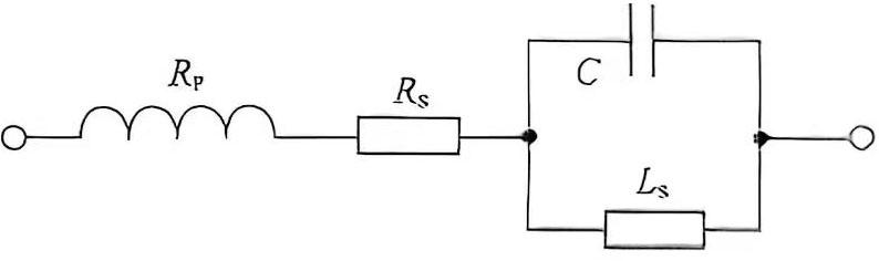
Figure 1 Capacitor Equivalent Circuit
1.1. Test Conditions
Typically, the conditions for measuring the dissipation factor, tanδ, for film capacitors are the same as those for measuring capacitance. For polyester and polypropylene film capacitors, an additional 10kHz test frequency is required to determine the dissipation factor for capacitors with CR < 1μF.
1.2. Relationship of Dissipation Factor with Frequency
If the inductive reactance, LS, is ignored and for f < fr (where fr is the oscillation frequency), the capacitor’s equivalent circuit shows that the dissipation factor, tanδ, is composed of the loss factor, tanδP, of the parallel resistance component, the loss factor, tanδS, of the equivalent series resistance component, and the loss factor, tanδD, of the insulating dielectric component. Thus, the overall loss factor of a film capacitor is:
tanà = tan¢, -tan8s + tandp (1)
Where (tan6p – 2nfC·R,; tan8s – 2πfC·Rs; tan8v w-g-1) represents the dielectric properties.
Because the parallel resistance component’s loss factor, tanδP, is relatively small and negligible over the entire frequency range, the presence of dielectric reactance (parallel impedance RP) effectively negligible the overall loss factor, even at very low frequencies (f << 1kHz). Therefore, in capacitor insulation characteristic analysis, the loss factor, tanδ, at low frequencies is determined solely by the dielectric component, tanδD. For small-capacity polypropylene film capacitors, the loss factor is virtually independent of frequency until the frequency reaches several megahertz, at approximately 10-4.
However, as frequency increases (f > 1kHz), the loss factor of the equivalent series resistance (ESR), tanδS (proportional to capacitance), increases rapidly until it becomes the dominant component of the loss factor curve. Figure 2 shows the relationship between the loss factor and the equivalent series resistance (ESR) of 10nF and 100nF polypropylene film capacitors and the frequency. The equivalent series resistance is the sum of the connection resistance (terminals), lead resistance, metal layer resistance, and electrode foil resistance.
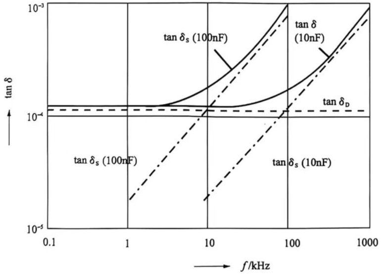
Figure 2 Relationship between the ESR and dielectric loss factor of polypropylene capacitors (0.1μF and 0.01μF) and frequency.
Figure 3 shows the relationship between the loss factor and frequency for various film capacitors. Because the dielectric properties of polyester film capacitors result in a significant dielectric loss, tanδD, the overall loss factor of polyester film capacitors is significantly higher than that of polypropylene and polystyrene film capacitors, especially at low frequencies.
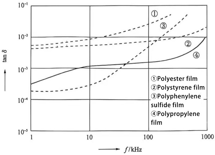
Figure 3 Relationship between the loss factor and frequency for capacitors with different dielectrics.
1.3. Relationship between the loss factor and temperature, humidity, and voltage.
Figure 4 shows the relationship between the loss factor and temperature for film capacitors. Among them, the loss factor of polypropylene film capacitors and polyphenylene sulfide film capacitors is independent of temperature within the -40℃ to 100℃ range. It begins to increase above 100℃, reaching a peak of approximately 4 x 10⁻³ at approximately 135℃. Polyester film capacitors exhibit the worst temperature dependence, ranging from 2 x 10⁻³ to 14 x 10-3. From -30℃ to 60℃, the loss factor decreases with increasing temperature, then begins to increase again above 80℃. The loss factor is relatively low between 50℃ and 80℃, reaching its lowest value at approximately 70℃.
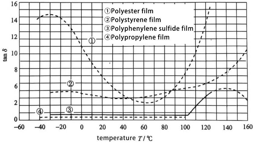
Figure 4 Relationship between the loss factor and temperature of capacitors with different dielectrics.
Generally, increased humidity reduces the insulation resistance (parallel resistance) of a capacitor. Therefore, the loss factor may increase in humid conditions. The loss factor of organic dielectric films is independent of voltage.
2 Insulation Resistance
2.1. Test Conditions
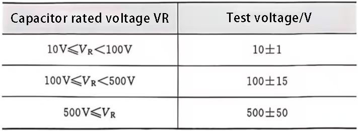
One of the key parameters for capacitor insulation performance is insulation resistance (Ris). This is calculated by determining the ratio of the input DC voltage to the current applied to the capacitor for 1 minute plus or minus 5 seconds. The test voltages specified in CECC30000 and IEC384-14, Section 5.2, are shown in Table 1.
Table 1 Rated Voltage vs. Test Voltage Relationship
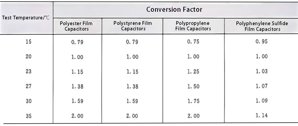
If the test is not performed at 20℃, the relative values must be converted to values at 20℃. Conversion relationships for commonly used dielectrics are shown in Table 2.
Table 2 Conversion Relationships for Common Dielectrics
In the datasheets of various capacitor models, insulation resistance (Ris) is given as the minimum transfer value and is obtained as a limiting value after “as-tested” testing. For capacitors rated >0.33μF, insulation resistance is typically given as a time constant, i.e., τ = Ris·CR.
2.2. Factors Affecting Insulation Resistance
As can be seen from the conversion coefficients in Table 2, insulation resistance is affected by temperature. Figure 5 shows the relationship between insulation resistance and temperature for commonly used dielectrics. Capacitor insulation resistance is also affected by humidity (the humidity factor of insulation resistance is negative).
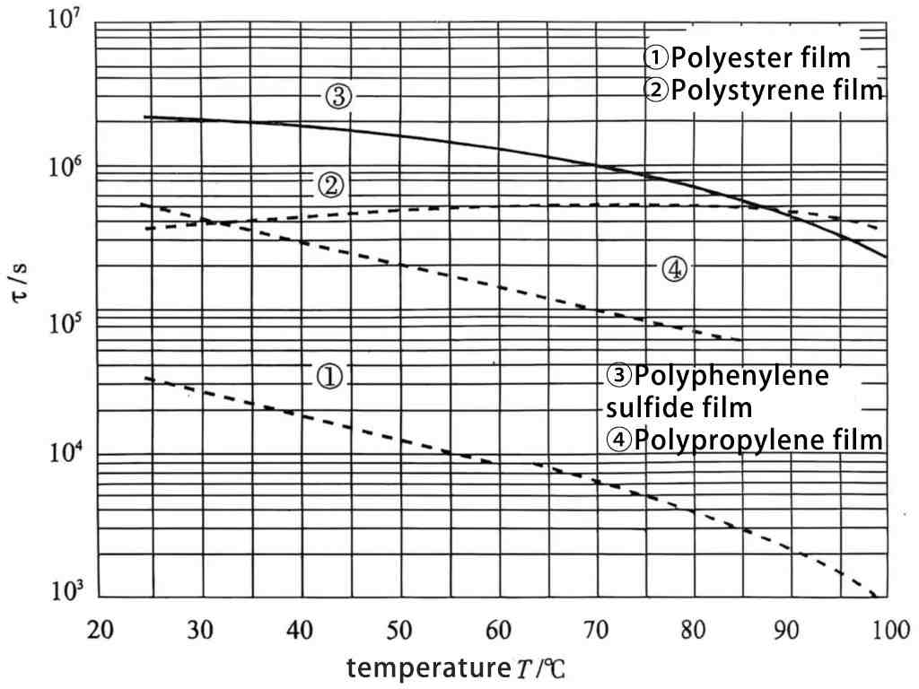
Figure 5 Relationship between insulation resistance and temperature for capacitors with different dielectrics