What are the voltage parameters of film capacitors? What do they mean? Why are there current parameters? The capacitor voltage includes rated voltage, DC dielectric strength/test voltage, maximum continuous voltage, AC voltage and AC current, pulse handling performance, pulse characteristics and other parameters.
1.Rated voltage
The rated voltage (VR) is the maximum DC voltage at which the capacitor can work continuously within the entire temperature range of the capacitor.
2.DC dielectric strength/test voltage
The DC test voltage of each specification of capacitor is given in the final inspection of capacitor products (100% electrical inspection). This DC voltage is also used for condition compliance testing (duration 60s) and quality consistency testing (duration ≤ 2s). If it is an EMI suppression capacitor, the (minimum) test voltage given in the corresponding standard can also be applied according to different application conditions.
Dielectric strength refers to the dielectric strength that the medium can withstand, generally expressed as a multiple or percentage of the rated voltage. This value varies with different capacitors, generally 150%~250% of the rated voltage, and you need to check the corresponding data sheet.
Test voltage refers to the sampling test of the capacitor before leaving the factory. Depending on the medium, it is usually 1.25~2.5 times the rated voltage.
Life test voltage: This test is carried out together with the temperature test. Usually, the test voltage is applied under the condition of the upper temperature limit (such as 85℃) where 100% of the rated voltage can be applied. This voltage is generally 125% or 150% of the rated voltage for 500h.
Whether it is the test voltage or the life test voltage, it reflects the dielectric strength of the capacitor medium. That is to say, the capacitor voltage is not necessarily broken down once it exceeds the rated voltage. There is a certain voltage safety margin, but the voltage on the capacitor should not exceed the rated voltage during use.
3.Maximum continuous voltage
The maximum continuous voltage (category voltage) is the voltage applied continuously at any temperature within the entire temperature range of the capacitor, which is the same as the rated DC voltage VR. In the whole temperature range, as the temperature rises to a certain value, some types of film capacitors need to reduce the rated voltage, as shown in Figure1. As can be seen from the figure, when the temperature exceeds 85℃, the rated voltage of polypropylene film capacitors needs to be reduced (linearly), and when the temperature reaches 100℃, it should be reduced to 70% of the room temperature; when the temperature exceeds 85℃, the rated voltage of polyester (polyester) film capacitors also needs to be reduced (linearly), and when the temperature reaches 125℃, it should be reduced to 50% of the room temperature; when the temperature exceeds 105℃, the rated voltage of polystyrene and polyphenylene sulfide film capacitors needs to be reduced (linearly), and when the temperature reaches 125℃, it should be reduced to 75%~80% of the room temperature. Among these media, polypropylene has the worst high-temperature withstand voltage performance, and polyphenylene sulfide is the best. According to the above conclusions, in practical applications, the highest temperature that may occur should be fully considered, and the type and rated voltage of the capacitor should be correctly selected.
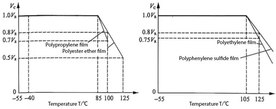
Figure 1 Relationship between rated voltage and temperature of film capacitor
4.AC voltage and AC current
The ability of a capacitor to withstand continuous (sinusoidal) AC effective voltage Vrms or AC effective current Irms depends not only on the frequency, but also on the three factors involved in the capacitor voltage performance: corona discharge voltage, power loss heat generation and maximum AC current (Figure 2).
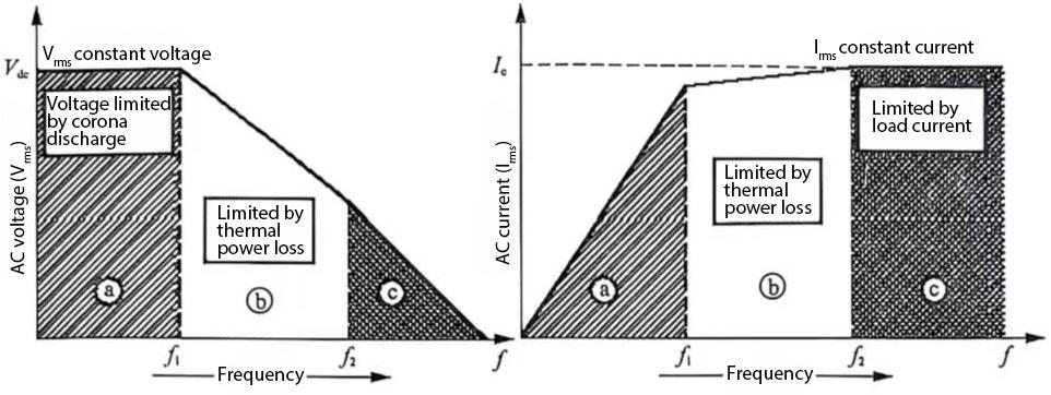
Figure 2 Relationship between capacitor and loaded AC voltage and AC current
(1) Region (a): With the beginning of corona discharge voltage Vdc as the limiting boundary
Below a certain frequency f1, the input AC voltage (alternating voltage) Vrms cannot exceed its threshold voltage Vdc. When the voltage is Vdc, corona discharge (partial discharge) begins, accompanied by violent vaporization of the capacitor, which will eventually reduce the dielectric (insulation) strength. Therefore, it is necessary to ensure that Vrms ≤ Vdc, for example, Irms ≤ Vdc·2πfC. This voltage limit is determined based on the internal structure of the capacitor (which determines the regional strength of the capacitor edge). This voltage limit is also related to the thickness of the insulating medium to a certain extent. The withstand capacitor voltage can be increased by adopting the internal series connection method (see Figure 3). Therefore, it is often seen that the size of capacitors with high rated voltage is longer, while the size of capacitors with low rated voltage is shorter.
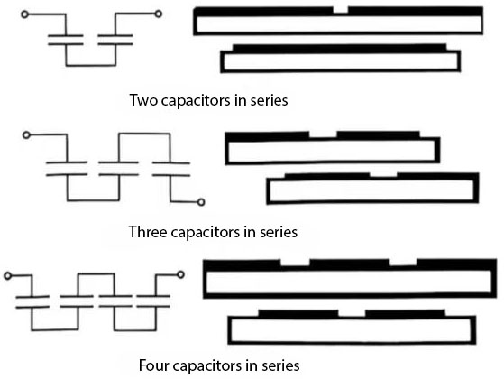
Figure 3 Internal series connection method of capacitors
(2) Region (b): Boundary limited by power loss and heat generation
When the frequency is higher than the frequency f1, the capacitor voltage and current will be limited by the heat caused by the loss on the ESR and the dielectric loss. At this time, the applied AC voltage must be reduced as the frequency increases to maintain the allowable dissipation power PE generated by the capacitor itself. This dissipation power is
![]() (1)
(1)
PE should be lower than the power PA that can be consumed in the form of heat energy from the surface area A of the capacitor:
![]() (2)
(2)
Where a is the heat conversion coefficient; A is the surface area of the capacitor; ∆T is the difference between the surface temperature of the capacitor and the ambient temperature.
To prevent permanent damage to the capacitor, the steady-state overtemperature T is obtained at the hottest part of the capacitor surface when the ambient temperature does not exceed a certain value, so that the power generated is equal to the power dissipated in the form of heat energy:
![]()
The maximum allowable AC voltage and AC current in this area are
![]() (3)
(3)
Simplified as follows:
![]() (4)
(4)
Frequency limit f is the maximum frequency under which the maximum permissible AC voltage V: is applied and the maximum permissible dissipation frequency is not exceeded:
![]() (5)
(5)
Thus, within a certain voltage range, f is inversely proportional to the capacitance, i.e. (![]() )
)
(3) Region (c): When the limiting frequency determined by the maximum current capacity is higher than the limiting frequency f, the permissible market AC voltage is limited by the current limit 1., which is the maximum current that can flow through the effective electrical connection part of the terminal (wire, metal layer, sprayed metal terminal, folded connection impedance and welding place, etc.) without overheating due to connection resistance loss. The capacitor voltage characteristics are closely related to the current characteristics, and the voltage limit here is essentially determined by the maximum permissible current.
The limiting frequency is
![]() (6)
(6)
In the data sheet of each model, the AC voltage characteristic curves allowed for different voltage ranges and capacitor models are given. Usually, in practical applications, loads with completely standardized sinusoidal waveforms are not used. However, in most cases, the load can be estimated accurately enough using a sinusoidal waveform. In special cases, the voltage or current waveform must be obtained by harmonic analysis.
Usually, the characteristic curves of the household appliance industry and frequency given in the data sheet are only general assumptions. In some strict cases, no clear conclusions can be drawn. This is particularly important. In these cases, the final conclusion must be drawn through actual testing of special circuits.
It should be noted that even if the AC load characteristic diagram of the capacitor gives the mains voltage range, standard film capacitors are basically not suitable for direct connection to the mains network. The main reason is that when directly connected to the mains, it is necessary to comply with the requirements of electrical safety regulations (referred to as safety regulations). At this time, X series and Y series EMI suppression capacitors are required, which have specific designs for capacitor voltage insulation and safety.
5.Pulse handling performance, pulse characteristics
Voltage change du/dt A large voltage pulse will cause a large current (spike current) in the capacitor, and its voltage rise rate can be considered as:
![]() (7)
(7)
Where Vpp and τ are the pulse voltage peak and rise time respectively. The peak current on the capacitor is
![]() (8)
(8)
This peak current generates heat at the junction between the metallized end face and the metal layer. The heat energy generated is
![]() (9)
(9)
Where R; is the internal resistance (ESR)
The pulse handling capability of the capacitor is determined by its internal structure. Usually, capacitors with bimetallized and foil electrodes will have a relatively high di/dt.
Apart from the different structures of the layers, capacitors with good outer layers have a basic advantage in pulse handling characteristics over capacitors with damaged surfaces. In principle, capacitors with good outer layers contain a large number of independent parallel individuals, and any damage only affects independent components.
6.Dielectric strength at low pressure (safety altitude)
The sparkover safety distance of the capacitor terminal decreases as the ambient pressure decreases. The capacitor can operate at a pressure as low as 40kPa, equivalent to an altitude of 7000m above sea level (about 23,000ft) without derating the capacitor voltage. If the application height exceeds this range, a special capacitor must be customized to ensure its insulation and reliability.