
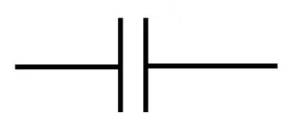
A capacitor symbol is two plates separated by a gap, with a lead leaving each plate. The gap is the dielectric and the plates are the electrodes, so the drawing is a picture of the part rather than an arbitrary mark. Once you know what each element of the symbol is doing, you can read polarity, adjustability and capacitor type straight off a schematic without looking anything up.
What the symbol cannot tell you is the capacitance or the voltage rating. Those live in the parts list, never in the drawing.
What Each Part of the Symbol Means
The two plates are drawn as straight lines when the capacitor can be connected either way round. When one plate is curved, the part is polarized: the straight plate is the positive terminal and the curved plate is the negative one. That convention exists because the curved plate is meant to suggest the metal can of an electrolytic capacitor, which is the negative electrode and the part that fails violently if it is reversed.
An arrow crossing the symbol at an angle means the capacitance is adjustable. A straight line with an arrow through it is a variable capacitor, used for tuning. An arrow with a T-shaped end marks a trimmer, which is adjusted once during calibration and then left alone. A small plus sign next to one plate is an explicit polarity mark, added whenever plate curvature might be hard to see at small print sizes.
IEC and ANSI Draw the Same Part Differently
There is no single worldwide capacitor symbol. Two conventions are in use, and mixing them in one schematic is a common source of confusion.
| Aspect | ANSI / IEEE | IEC 60617 |
|---|---|---|
| Where it is used | North America and designs derived from US schematics | International and European drawings, increasingly global |
| Non-polarized style | Two straight parallel plates | Two parallel rectangular bars, more box-like |
| Polarized style | Straight plate positive, curved plate negative, often with a plus sign | Boxed symbol with an explicit plus marking |
In practice the plus sign is the one marker you can trust across both systems. Curvature is a strong hint under ANSI, but under IEC the polarity may be carried by the plus alone, so a reader who only looks for a curved plate will miss it. EDA tools ship both sets and default differently: KiCad leans IEC, while Altium, OrCAD and LTspice commonly start from ANSI. Pick one convention per project, record it in the title block, and do not mix them on the same sheet.
The Three Symbol Families
Non-polarized symbols cover ceramic, film, mica and supercapacitors, and also the non-polarized aluminium electrolytics sold for AC or crossover duty. They are drawn as two identical plates.
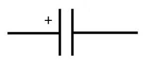
Polarized symbols cover aluminium electrolytics and tantalums: one straight plate, one curved plate, plus sign on the positive side. These are the capacitors that must not be reversed, and the symbol exists mainly to make that impossible to overlook.
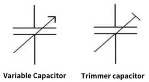
Variable and trimmer symbols add an arrow. A plain diagonal arrow means continuously adjustable; an arrow with a flat end means a trimmer set once at calibration. These turn up in RF tuning, oscillators and filter alignment.
Reading Polarity Off a Real Capacitor
Once you have a physical part in hand, the symbol is no longer the guide. Electrolytics carry their own markings, and they are more reliable than any inference from shape.
- A stripe or band down one side, usually printed with minus signs, marks the negative terminal. This is the most dependable indicator and it is present on almost every aluminium electrolytic.
- On radial parts, the longer lead is positive. On axial parts the leads are usually cut to equal length, so the stripe is the only cue.
- A plus sign is sometimes printed next to the positive terminal, but it is less common than the negative stripe.
- Reverse connection heats the part, raises leakage and can vent the case. There is no safe way to guess.
Checking Polarity with a Multimeter
The capacitance range on a multimeter measures capacitance. It has no polarity, and it will not show a negative reading when you reverse the leads, so a procedure built on that reading cannot work.
What does work is comparing the two directions on the resistance or diode-test range. An electrolytic capacitor leaks less when it is connected the right way round, so the orientation that settles at the higher resistance is the correct one. Follow these steps, with the capacitor discharged and out of circuit first.
- Discharge the capacitor through a resistor, not by shorting the leads of a large part.
- Set the meter to resistance or diode test, not capacitance.
- Note the reading with the leads one way round, holding long enough for it to settle.
- Reverse the leads and note the second reading.
- The direction with the higher resistance, or the one that drifts up towards open circuit, is the correct orientation.
- If both directions read the same, the part is either non-polarized or faulty. Confirm against the printed stripe before fitting it.
This test confirms what the marking already told you. It is a useful check on a salvaged part with an unreadable sleeve, not a substitute for reading the marking in the first place.
FAQ
What is the symbol for a capacitor?
Two parallel plates with a gap between them and a lead at each plate. Under IEC 60617 the plates are drawn as rectangular bars; under ANSI they are straight lines.
How do I tell a polarized capacitor symbol from a non-polarized one?
Look for a curved plate or a plus sign. Two identical straight plates mean non-polarized. A curved plate or an explicit plus means polarized, and the part must be fitted the right way round.
Can a multimeter tell me which lead of an electrolytic is positive?
Not on the capacitance range. Use the resistance or diode-test range and compare the two directions: the orientation with the higher resistance is correct. The printed stripe is faster and more reliable.
Why do some schematics use boxes instead of plates?
That is the IEC 60617 style. Both conventions describe the same component, but they should not be mixed within one drawing set.
Matching the Symbol to the Part You Are Ordering
When a symbol tells you the capacitor is polarized and non-adjustable, that narrows the order to an aluminium electrolytic or a tantalum. A non-polarized symbol points to film, ceramic or a non-polarized electrolytic, which is where most film capacitor parts sit. If the schematic marks an electrolytic in a power rail, the electrolytic capacitor range is the place to look for a match on capacitance, voltage and case size. Send the symbol type, the capacitance and the working voltage to coco@xuanxcapacitors.com, or contact us here, and we will confirm the equivalent part.