Capacitors are one of the most failure-prone components in electronic circuits. Whether you’re repairing a power supply, troubleshooting a PCB, or maintaining industrial equipment, knowing how to test capacitors is an essential skill.
In this guide, we’ll cover 8 proven capacitor testing methods, from basic multimeter checks to advanced engineering techniques.
Before You Test a Capacitor
When learning how to test capacitors, safety is the top priority!
- Throughout the testing process, ensure the capacitor is fully discharged to prevent residual charge from causing personal injury or damaging your multimeter.
- Before testing, always disconnect at least one lead of the capacitor from the circuit to avoid interference from parallel paths and eliminate the risk of electric shock.
- Strictly avoid applying a voltage exceeding the capacitor’s rated voltage; failure to do so may result in bursting, electrolyte leakage, or fire.
- When handling high-voltage or high-capacitance capacitors, wear appropriate protective gear, such as insulated gloves and safety goggles, to ensure safe capacitor testing.
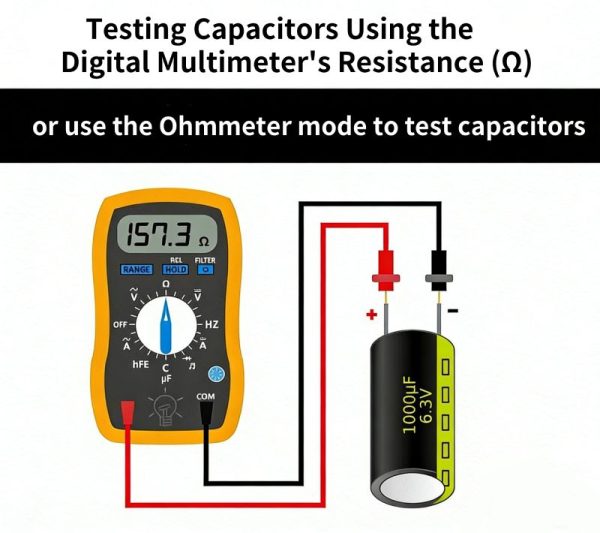
I. Digital Multimeter Resistance Mode Testing Method
Utilizing the Ohm (Ω) range of a digital multimeter, this method assesses the capacitor’s condition by observing the changes in resistance during its charging and discharging process. It is simple to operate and applicable to most scenarios.
Operation Steps
1. First, thoroughly discharge the capacitor to prevent residual voltage from damaging the multimeter or affecting the measurement readings.
2. Set the multimeter to the resistance range; it is recommended to select a range of 1kΩ or higher.
3. Connect the test leads to the corresponding capacitor terminals: connect the red lead to the positive terminal and the black lead to the negative terminal (this distinction is necessary for polarized capacitors; for non-polarized capacitors, the connection order does not matter).
4. Observe the value displayed on the screen: initially, a specific resistance value will appear, followed by a rapid transition to “OL” (Open Circuit) or the infinity symbol (∞).
Interpreting the Results
If every measurement follows the pattern of “initial resistance value → instantaneous shift to OL/infinity,” it indicates that the capacitor is in good working order. Conversely, if the value remains static, stays fixed at a specific number, or immediately displays “OL,” it signifies that the capacitor is damaged.
Using a digital multimeter in this way is a fundamental step in how to test capacitors, especially for beginners and DIY electronics troubleshooting.
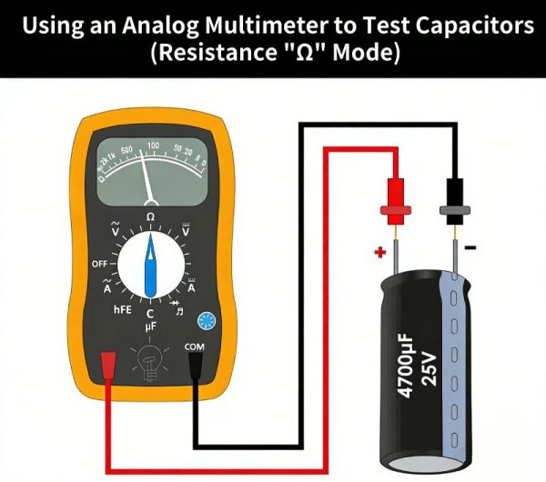
II. Analog Multimeter Resistance Mode Testing Method
Analog multimeters, also called AVO meters, rely on the deflection of a pointer to show changes in resistance. This provides a more intuitive visual representation of a capacitor’s charging and discharging process. For experienced technicians and electronics enthusiasts, this method is a reliable way to learn how to test capacitors quickly and effectively.
Operation Steps
-
Fully discharge the capacitor to eliminate any residual internal charge.
-
Turn the analog multimeter’s rotary knob to the resistance range, selecting a high-resistance setting.
-
Connect the test leads: black lead (COM) to the negative terminal, red lead to the positive terminal.
-
Observe the pointer’s deflection carefully and note the dynamic pattern during charging and discharging.
Interpreting the Results
-
Short-Circuited Capacitor: Pointer swings directly to the low-resistance zone and remains there, indicating extremely low resistance.
-
Open-Circuited Capacitor: Pointer shows no deflection, indicating no charging or discharging response.
-
Good Capacitor: Pointer initially deflects, then slowly returns to infinity.
Using an analog multimeter in this way is an important technique for electronics troubleshooting and a key step in how to test capacitors for both professionals and hobbyists.
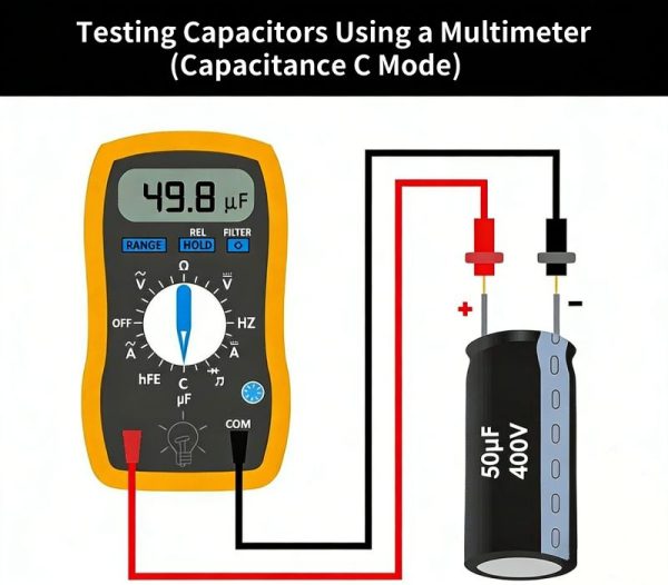
III. Multimeter Dedicated Capacitance Mode Testing Method
This method is applicable only to digital or analog multimeters equipped with a dedicated capacitance measurement function (typically labeled C or F). It allows for the direct reading of the capacitor’s actual capacitance value, offering the highest level of measurement accuracy. This technique is an essential step in how to test capacitors. Furthermore, this mode is capable of testing small-capacity components, such as surface-mount (SMD) capacitors and ceramic capacitors. For reliable performance in your projects, consider our high-quality SMD and electrolytic capacitors.
Procedure
-
After ensuring the capacitor is fully discharged, desolder it from the circuit board to prevent interference from other components.
-
Set the multimeter dial to the capacitance measurement range, selecting a range that corresponds to the nominal value of the capacitor being tested.
-
Connect the red test lead to the capacitor’s positive terminal and the black test lead to the negative terminal, ensuring a firm connection.
-
Once the reading stabilizes, compare the value displayed on the meter with the rated capacitance marked on the capacitor’s casing.
Result Interpretation
Capacitors typically have a standard tolerance of ±10% to ±20%; if the reading falls within this range, the capacitor is considered in good condition. If the reading is significantly lower than the nominal value, shows no reading at all, or deviates drastically, it indicates that the capacitance has degraded or failed, and the capacitor must be replaced.
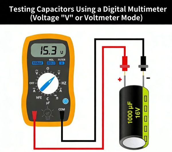
IV. DC Voltage Range Testing Method
Using the DC Voltage (V-) range on a multimeter, this method assesses the capacitor’s condition by observing how well it retains voltage after being charged and discharged. It is suitable for testing both polarized and non-polarized capacitors, provided that the capacitor’s rated voltage is known.
Procedure
1. Disconnect one of the capacitor’s leads (or completely remove it from the circuit board) to prevent current diversion through parallel circuit paths.
2. Verify the rated voltage marked on the capacitor’s casing; strictly avoid charging the capacitor with a voltage exceeding this rating.
3. Briefly charge the capacitor using a DC power source with a voltage lower than the capacitor’s rated voltage (e.g., using a 9V battery for a 16V capacitor), ensuring that the positive and negative terminals are connected correctly.
4. Set the multimeter to the DC Voltage range, place the test leads against the capacitor’s terminals, and read the initial voltage value.
Result Interpretation
If the initial voltage reading is close to the voltage of the charging source, it indicates that the capacitor is storing charge normally and is in good condition. If the voltage value is extremely low—or shows almost no reading at all—it signifies that the capacitor has failed to retain charge.
Critical Warning: The charging voltage *must* be kept below the capacitor’s rated voltage to prevent the capacitor from bursting or leaking electrolyte.
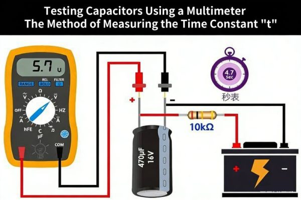
V. RC Time Constant Measurement Method
By calculating the capacitor’s charge and discharge time constant, this method allows for the precise determination of its actual capacitance. It is suitable for testing capacitors with clearly legible markings and no visible physical damage; measurement accuracy is further enhanced when used in conjunction with an oscilloscope.
Core Principle
As a capacitor charges through a fixed resistor, the time required for its voltage to reach 63.2% of the applied external voltage constitutes the time constant, denoted as τ. The formula is: $$\tau = R \times C$$ (where R is the known resistance value and C is the capacitance). Similarly, the time required for the capacitor to discharge down to 36.8% of its voltage can be calculated using the same principle.
Operating Steps
1. Remove the capacitor from the circuit and ensure it is thoroughly discharged; prepare a resistor with a known resistance value (5–10 kΩ is recommended).
2. Connect the resistor and capacitor in series, and then connect them to a stable DC power supply (9V or 12V).
3. Start a stopwatch and monitor the capacitor’s voltage until it rises to 63.2% of the power supply voltage; record the elapsed time.
4. Substitute the recorded time into the formula $$C = \tau / R$$ to calculate the actual capacitance, and then compare this calculated value against the capacitor’s nominal (rated) value.
Result Interpretation
If the deviation between the calculated capacitance and the nominal value falls within a tolerance range of ±10% to ±20%, the capacitor is considered normal. If the deviation is excessive, it indicates that the capacitance has degraded, and the capacitor is no longer capable of functioning correctly.
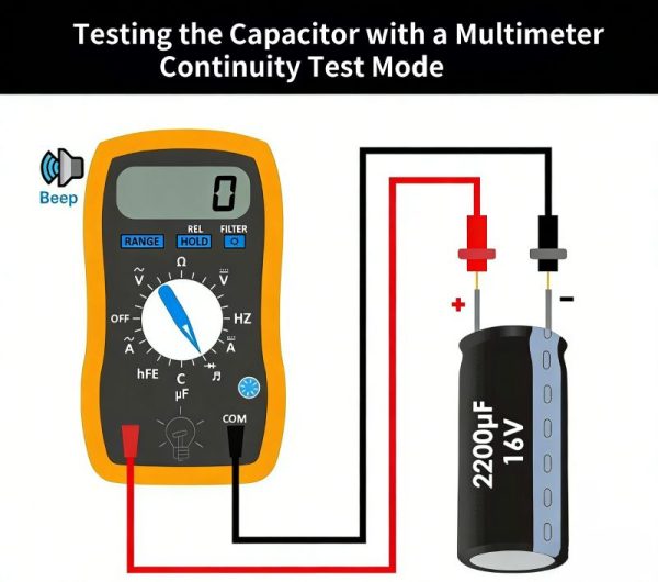
VI. Multimeter Continuity Test Method
This method uses the continuity testing function of a digital multimeter, combined with audible beeps and indicator light feedback, to quickly identify short-circuit or open-circuit faults in a capacitor. It is simple to operate and an effective technique when learning how to test capacitors.
Procedure
-
Disconnect power to the device, remove the capacitor from the circuit, and ensure it is fully discharged.
-
Set the multimeter to continuity test mode, then connect the red probe to the capacitor’s positive terminal and the black probe to the negative terminal.
-
Observe the buzzer and indicator light, noting any changes in response.
Result Interpretation
-
Functional Capacitor: The buzzer sounds (or the indicator light briefly turns on) and then stops immediately; the display shows “OL” (Open Loop).
-
Open-Circuit Capacitor: No buzzer sound, no indicator light, indicating no electrical conduction.
-
Short-Circuit Capacitor: The buzzer sounds continuously, and the indicator light stays on, indicating a permanent conductive path.
Using continuity testing is a fast, beginner-friendly way to check capacitors and a key step in how to test capacitors before performing more advanced measurements.
VII. Visual Inspection Method
No multimeter is required for this method. By carefully observing the capacitor’s exterior for visible defects, you can quickly identify potential failures. This approach is ideal for a preliminary check before using more precise testing tools and is an important step in learning how to test capacitors effectively.
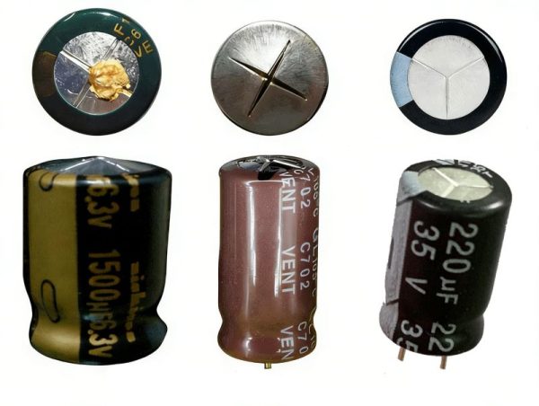
Failure Characteristics of Electrolytic Capacitors
-
Bulging or Cracked Top: The K-, T-, or X-shaped pressure relief vent on the capacitor’s top may appear swollen, cracked, or deformed. Often, you might notice leakage of black, white, or orange electrolyte fluid—one of the most common signs that the capacitor has failed.
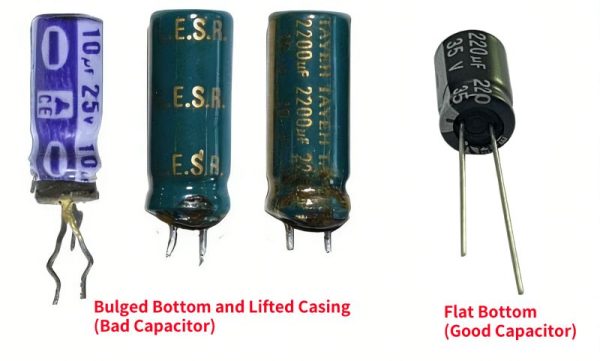
- Bulging Bottom or Lifted Casing: If the internal pressure inside the capacitor cannot escape through the top vent, it may push against the bottom rubber seal, causing the base to bulge outward and the outer casing to lift. Observing such physical deformities is a quick and effective step when learning how to test capacitors visually.
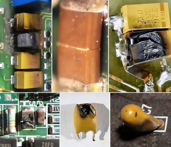
When learning how to test capacitors visually, it’s important to carefully examine ceramic and SMD components for external defects, which often indicate failure:
-
Cracked or Damaged Casing: Look for cracks, puncture marks, or any physical deformation of the capacitor body.
-
Surface Discoloration: Signs of scorching, blackening, or corrosion on the capacitor surface suggest overheating or electrical stress.
-
Damaged Leads or Pads: Check for broken, detached, or heavily oxidized pins or solder pads, which can prevent proper electrical connection.
Visual inspection of these defects is a simple but effective step in how to test capacitors before using multimeters or other measurement tools.
VIII. Professional High-Voltage Spark Test Method (For Professionals Only)
This method carries a significant risk of electric shock and capacitor explosion. It is strictly forbidden for non-professionals to attempt this procedure. It should only be utilized in emergency repair scenarios where no other diagnostic tools are available, and strict safety precautions must be observed at all times.
Procedure (Safety First)
1. Remove the capacitor from the circuit board and discharge it completely; wear safety goggles and insulated gloves.
2. Connect a high-power current-limiting resistor (1 kΩ to 10 kΩ, 5 to 50 W) in series to prevent excessive charging current.
3. Use a 24 V DC power supply (or a 220 V AC power supply—which requires a series resistor) to charge the capacitor briefly for 1 to 4 seconds.
4. Disconnect the power supply, then use an insulated tool to quickly short-circuit the capacitor’s terminals.
Interpreting the Results
If a bright, intense electrical spark is observed during the short-circuiting, it indicates that the capacitor is storing charge normally and is in good condition; a weak spark or the absence of a spark signifies that the capacitor has failed.
Conclusion
Learning how to test capacitors is an essential skill for anyone working with electronic circuits, from hobbyists to professional technicians. By using the methods outlined in this guide—digital and analog multimeters, capacitance measurement, DC voltage testing, RC time constant calculation, continuity tests, visual inspection, and professional techniques—you can quickly identify faulty capacitors and ensure your circuits operate safely and efficiently.
Remember, always prioritize safety: fully discharge capacitors before testing, follow proper procedures, and wear protective equipment when handling high-voltage components.