What happens when AC power is applied to the capacitor? Capacitors behave differently from resistors-in resistors, the flow of electrons is proportional to the voltage drop; in capacitors, when it is charged or discharged to a new voltage level, it resists changes in voltage by absorbing or releasing current . When providing direct current (DC) to the capacitor, as long as the power supply voltage exists, it will be charged to the value of the applied voltage like a temporary energy storage, and then hold or maintain this charge indefinitely. If there is any change in the voltage, a charging current will flow in the capacitor to resist this change at a rate equal to the rate of change of the charge on the capacitor plate.
As shown in Figure 1, let’s study a circuit with only capacitors and AC power. Facts have proved that there is a 90° phase difference between the current and the voltage, and the peak value of the current is 90° (1/4 cycle) ahead of the peak value of the voltage. AC power will generate oscillating voltage. The greater the capacitance value, the more charge must flow in order to establish a specific voltage on the plate, and therefore the greater the current. The higher the voltage frequency, the shorter the time available to change the voltage, so the current must be larger. Therefore, the current will increase as the capacitance and frequency increase.
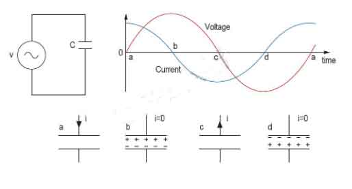
Figure 1: Circuit with only capacitors and AC power supply and its working principle.
Capacitive AC circuit
A purely capacitive AC circuit is a circuit that only contains AC power and capacitors, as shown in Figure 2. The capacitor is directly connected across both ends of the AC power supply voltage. As the power supply voltage increases and decreases, the capacitor will charge and discharge. Current will first flow through the circuit in one direction and then flow in the other direction. However, no current actually flows through the capacitor. Electrons accumulate on one plate, and then are discharged from the other plate in rapid succession, giving the impression that current flows through the insulator that separates the plates.
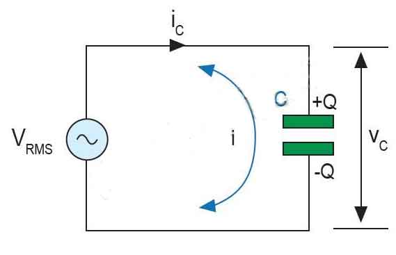
Figure 2: Pure capacitive AC circuit.
Capacitive reactance
The current flowing in the capacitor is proportional to the rate of change of the voltage across the capacitor. The capacitive reactance in a purely capacitive circuit hinders the current in the AC circuit. As with resistance, the unit of measurement of reactance is also ohms. Therefore, in order to distinguish it from the pure resistance value, reactance is represented by the symbol X. Since capacitive reactance depends on the value of the capacitor (in farads) and the frequency of the AC waveform, it can be expressed by the following formula.
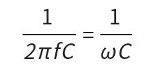
This formula shows that if the frequency or capacitance value is increased, the total capacitive reactance will decrease. Similar to an ideal conductor, when the frequency approaches infinity, the capacitive reactance of the capacitor will decrease to zero.