1.General Principles of Evaluation for shunt Capacitor Device
The basic score, test score, family defect score, and defect score of each device in the AC and DC filters and shunt capacitor device are calculated comprehensively to obtain the comprehensive score of the AC and DC filters and shunt capacitors, as shown in formula (1).
![]() (1)
(1)
Where B–basic score;
T–test score;
F–family defect score;
Q–defect score.
Except for the basic score which is a percentage score, the test score, family defect score, and defect score are all coefficient scores between 0 and 1, which should be noted when scoring.
2. Basic score (B) for shunt capacitor device
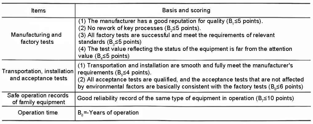
(1) The basic score of the equipment refers to the evaluation of the basic information of the equipment. The basic score can be evaluated by referring to Table 1 and formula (2). The full score of the basic score is 100 points. In general, the basic score of the equipment is greater than 80 points. The overall basic score of the filter and shunt capacitor device is the lowest basic score of each device. The detailed indicators of the basic evaluation score of the equipment can be referred to Table 2.
Table 1 Equipment basic score reference
![]() (2)
(2)
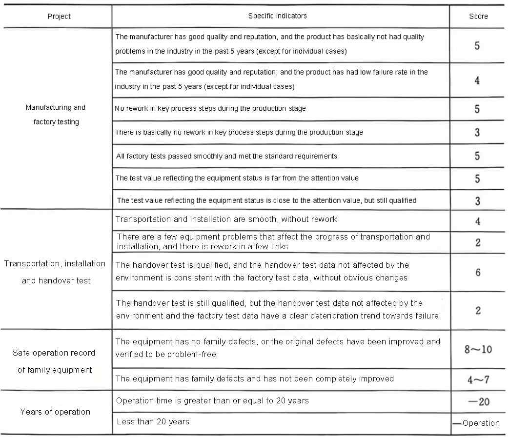
Table 2 Equipment basic score detailed indicator table
(2) Basic score calculation example. Example description: ① The manufacturers of the reactors, resistors, lightning arresters, and current transformers of the filter and shunt capacitor device in a converter station are all well-known domestic manufacturers with a good reputation. In the past five years, there have been no major quality problems (generally referring to the poor product quality caused by unreasonable manufacturer design, serious problems in key production processes, etc., which have been officially reported by relevant companies); ② The supplier of the capacitor equipment of the converter station has significantly higher fault damage than other manufacturers in the past one or two years. The capacitor equipment has passed the factory test, but some test state values are close to the attention value, and the handover test value has a large deviation from the factory test; ③ There is no rework during the equipment installation process.
The following analysis can be obtained from the above description: The basic scores of reactors, resistors, lightning arresters, and current transformers can all reach 100 points. Basic score of capacitors: 13 points for manufacturing and factory testing, 6 points for transportation, installation, and handover testing, 10 points for equipment without family defects, and the total basic score of capacitors is 60+29=89 (points).
Therefore, the basic score of the filter and shunt capacitor device composed of the above equipment installed on site takes the lowest basic score of all equipment, and the basic score of the filter and shunt capacitor device is 89 points.
3. Family defect score (F) for shunt capacitor device
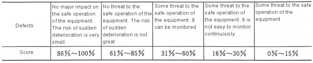
When the equipment has a family defect, the status score of those equipment that have not yet occurred or detected the family defect should be evaluated by formula (3) before the hidden danger is eliminated to evaluate the impact of the family defect. When calculating the family defect score, / is determined based on the location and nature of the defect (refer to Table 3, the value principle of ƒ).
Table 3 ƒ Value selection principle
![]() (3)
(3)
Where N–the total number of family equipment;
n–the number of equipment with the family defect (N>n≥1).
If the hidden dangers involving family defects have been eliminated, that is, their impact is no longer considered,
The following example explains the process and precautions for evaluating family defects in shunt capacitor device.
Taking capacitors as an example, the situation description: During the maintenance process, a converter station found that the capacitance of quite a few faulty capacitors was larger than the rated value.
Situation analysis: As can be seen from the previous chapters, the capacitance value is larger than the rated value, indicating that the fuse in the capacitor element is not reliably blown when a single capacitor element fails, resulting in a large parallel series element being short-circuited. If it is an individual case, the capacitance value of the faulty capacitor should not be larger than the rated value in large quantities, which obviously violates the original design intention of the internal fuse of the capacitor element. After being recognized by relevant units or institutions, the unreliable blowing of the internal wire can be determined as a family defect. Generally, family defects are closely related to the production process and material selection of the product batch. Before the process and materials are improved, such failures caused by a certain specific reason may exist in large numbers.
After determining the family defect, the family defect score should be included in the evaluation of the batch of products (even if some capacitors have not yet exposed the family defect and are normal equipment). This is also the difference between the family defect and the general defect score (general defects are included in the score if they exist, and not included in the score if they do not exist or have been eliminated).
The value of the family defect formula is determined, N is the total number of family defects (generally refers to the number of products of the same batch within a certain range or a certain area, which is relative). The wider the sampling of N and the larger the range, the more reasonable the calculation. In most cases, the unit where the unit is located will count the number of products of the batch used by the unit. For example, a converter station uses 7892 capacitors of this batch from this manufacturer (of course, this is a relative concept, and capacitors of this batch may also be found in other places). There are 87 capacitors with large capacitance values and the fuses in the capacitors fail to operate reliably. The formula (4) calculates:
![]() (4)
(4)
Formula (4) needs to further determine the value of ƒ, which is determined based on the location and nature of the defect. According to the value selection principle of Table 3 ƒ and the degree of influence of the family defect on the equipment, the family defect such as the unreliable action of the fuse in the capacitor is a major factor that seriously affects the capacitor equipment and poses a real threat to the safe and stable operation of the filter and parallel capacitor equipment. The conservative value can be set as the upper limit of 0.15, thus:
![]()
Notes on family defect evaluation:
(1) After the fuse fault in the capacitor is determined to be a family defect, even if there are only a few or even no products of the same process and batch in other stations that have this fault, the status score should also consider the family defect score.
(2) The first condition for a family defect is that the relevant unit determines that the fault or equipment hidden danger is a family defect. The determination of a family defect is generally determined by at least the provincial grid company or above, which is completely different from the determination of a defect.
(3) The person who conducts the family defect evaluation of the equipment must be an experienced professional and have a good understanding of the structural principles of the equipment (otherwise, it is easy to cause large deviations when some values need to be obtained by human intervention according to the regulations) in order to make a relatively reasonable evaluation.
(4) The determination of the N(n) value in the family defect evaluation is generally obtained through reasonable statistics of the number of equipment applications within a certain range.
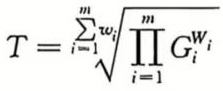
4. Test scoring method (T)
The test score is the weighted geometric mean of the scores of individual test items. The score of a single item is between 0% and 100%, and 100% corresponds to the state quantity of each item in the item being far below the attention value or warning value, and there is no obvious deterioration trend. Suppose a device has undergone m single tests, the score of the i-th test is Gi, and the weight is Wi; (take 1 when not given), then the test score T can be expressed by formula (5):
 (5)
(5)
4.1 Single test item scoring method-conventional method
This method is applicable to the analysis of positive degradation and negative degradation state quantities with attention value or warning value requirements
Suppose the attention value is xz, the warning value is xj, and the values of the last three tests are x, x1, and x2, where x is the current test value, x1 is the test value t1 years ago (relative to x), and x2 is the test value t2 years ago (relative to x), and t2>t1. In the following formulas, if the state quantity gives a warning value, then xˊ=xj; if the state quantity gives a attention value, then xˊ=1.3xz (positive degradation) or xˊ=xz/1.3 (negative degradation). The single test scoring method is shown in formula (6) to formula (12), where xƒ is the average value of the state quantity in similar new equipment. If there is no such value, it is replaced by the factory or acceptance test value of the equipment.
(1) When there is only one test record (i.e. x1 and x2 do not exist):
![]() (6)
(6)
In formula (6), when G<0, let G=0; when G>100, let G=100.
The following is a calculation example of the current test value of the arrester under 0.75 DC reference voltage in the AC and DC shunt capacitor device filter device.
The leakage current of a lightning arrester under 0.75 times DC in a converter station filter is 15μA when it is installed on site. According to Q/GDW506-2010 “Guidelines for the Status Evaluation of AC Filter and shunt Capacitor Device in High Voltage DC Transmission”, the attention value of this test item is 50μA, and the attention value of 15μA is far from exceeding the attention value. When the equipment is put into operation after completing the infrastructure handover test, it is necessary to evaluate the equipment results. The evaluation method of this test project is as follows:
Since there is only one test project, the calculation is based on formula (6). As the average value of xf in similar products is not easy to obtain as an operation and maintenance unit, the factory test value is selected here (which can be found in the factory test report). The leakage current value of the arrester at 0.75 times the DC reference voltage is 14.5μA.
![]()
![]()
There is only one test record and the single test score is 0.99.
(2) There are 2 test records (i.e. x2 does not exist):
Positive degradation is shown in formula (7):
![]() (7)
(7)
Negative degradation is shown in formula (8):
![]() (8)
(8)
When there are 2 test records, the algorithm is as follows: Taking the leakage current of the arrester at 0.75 times the DC reference voltage as an example (the state quantity of the arrester leakage current test is a positive degradation state quantity), when the first The leakage current value of the one-year test is 16μA, then x1=15μA (the acceptance test value one year ago), x=16μA (the current test value), substituting into formula (7) to obtain:
![]()
![]()
Then there are 2 lightning arresters with a leakage current score of 0.95 at 0.75 times the reference voltage.
(3) If there are 3 or more tests, select the values of the most recent 3 tests:
Positive degradation is shown in formula (9):
![]() (9)
(9)
Negative degradation is shown in formula (10):
![]() (10)
(10)
When there are 3 test records, the algorithm is as follows: still taking the leakage current of the arrester at 0.75 times the DC reference voltage as an example, when the test result of the project in the second year is 15.6μA, the values in formula (7-9) are: x=15.6μA (current value of leakage current), x1=16μA (leakage current value one year ago), x2=15μA (leakage current value two years ago), and the above values are Substituting into formula (9), we get:
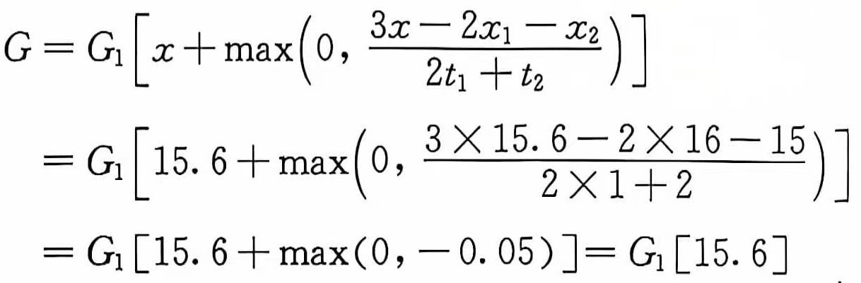
![]()
Then there are 3 leakage current records at 0.75 times the reference voltage, and the score is 0.978.
The above uses a specific example to introduce the state quantity calculation method of the positive degradation test.
4.2 Single test item scoring method
This method is suitable for state quantity analysis with positive and negative deviation requirements.
Assume that the current test value of a state quantity of the converter station is x, and the zero deviation value (usually the initial value or rated value) is x0, then the deviation (E) of x is as shown in formula (11)
![]() (11)
(11)
Assume that the allowed positive deviation is k+, and the allowed negative deviation is k–, and the scoring method is as shown in formula (12):
![]() (12)
(12)
When G≤0, let G=0.
The following uses the capacitor bank bridge arm capacitance test value (this state quantity belongs to the deviation degradation state quantity, and only the current test value is used when the deviation degradation is scored) as an example to illustrate the calculation method of using this type of test item as a single state quantity score. It is known from Q/GDW506-2010 that the bridge arm capacitance value deviation should not exceed ±2%. The following uses a domestic converter station as an example to illustrate the calculation method of deviation degradation. When the measured value of the current arm capacitance is x=1.082μF and the rated value of the bridge arm is x0=1.084μF, the x deviation (E) can be obtained according to formula (11) as follows:
![]()
![]()
![]()
Then the deviation degradation score is 91.2%.
Based on the state quantities of the test items selected in the above examples (assuming that the evaluation of other test state quantities is 1), the total test score of the filter and parallel capacitor is
![]()
The weight values of the above test state quantities are obtained according to Q/GDW506-2010: the weight of the state quantity of 0.75 times the leakage current of the lightning arrester is 3, and the weight of the state quantity of the bridge arm capacitance of the filter and parallel capacitor capacitor group is 4.
5. Equipment defect score (Q)
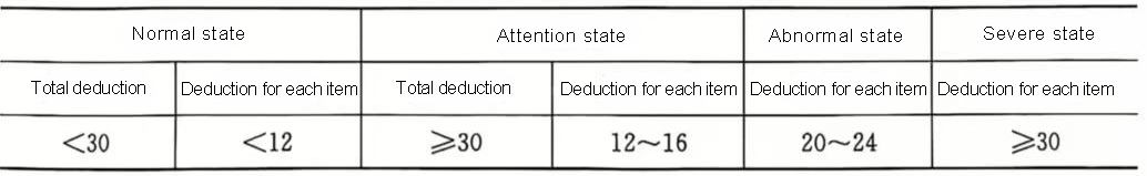
Each equipment defect of AC and DC filters and shunt capacitors is scored, and the equipment defect level is divided according to the total defect deduction and single defect deduction. Defect scores are divided into four levels according to the severity: severe state, abnormal state, attention state, and normal state. Each defect score level corresponds to a defect score coefficient. The normal state Q is 1, the attention state Q is 0.7~0.9, the abnormal state Q is 0.4~0.6, and the severe state Q is 0~0.3.
When the total deduction of all defect state quantities reaches the provisions of Table 4, it is regarded as a normal state; when the single deduction of any defect state quantity or the total deduction of all defect state quantities reaches the provisions of Table 4, it is regarded as a attention state; when the single deduction of any defect state quantity reaches the provisions of Table 4, it is regarded as an abnormal state or a severe state.
Table 4 Overall evaluation standard table for equipment defects
The defect score should be the existing defects that have not been eliminated, and the defect state quantity score of the participating equipment. Before scoring the defects of the filter and shunt capacitor, collect all the equipment defects of the group of filters or shunt capacitor device. For example, the uneliminated defects collected by the 3615 HP3 filter of a domestic converter station are shown in Table 5.
Table 5 Uneliminated defects of 3615 HP3 filters in a domestic converter station
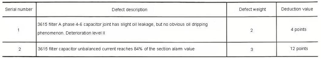
The maximum deduction for a single item of this group of filters is 12 points, and the total deduction is 16 points. According to the regulations Q/GDW506-2010, the more serious deduction reasons are taken, and the defect evaluation of this group of filters is in the attention state, which is the lower limit of the deduction value in the attention state. After a comprehensive comparison, the defect evaluation coefficient is determined to be 0.85.
In summary, through the above-mentioned filter and parallel capacitor basic scoring examples, family defect scoring examples, test scoring examples, and defect scoring examples, assuming that these examples are the actual conditions of a group of AC filter evaluations, the overall comprehensive score of the filter can be obtained. According to formula (6-1), the following is obtained:
Equipment comprehensive score G=B×F×T×Q=89×0.2332×0.94×0.85=16.58 (points).
If the filter does not have family defects, the equipment comprehensive score G=B×F×T×Q=89×0.2332×0.94×0.85=71 (points).
From this, it can be seen that once it is characterized as a family defect, it will have a very large impact on the equipment score, which may cause the equipment to be in a normal state. As a result, due to the existence of family defects, the equipment score is suddenly classified as a serious state, which will also have a huge impact on the maintenance strategy.