1. Classification and characteristics of ceramic dielectrics in ceramic capacitors
The ceramic dielectric used in ceramic capacitors has a high or even very high dielectric constant, which is an important material basis affecting the Performance of Ceramic Capacitors. Ceramic dielectrics are generally divided into three categories: Class I is an ultra-stable ceramic dielectric material, according to the American Electrical Industry Association (EIA) standard, such as COG (this is the number 0, not the letter O; some literature mistakenly writes it as COG) or NP0 (this is the number 0, not the letter O; some literature mistakenly writes it as NPO), and the CC series models according to the Chinese standard [temperature coefficient is (0±30)×10−6∘C−1]. This dielectric is extremely stable, has a very low temperature coefficient, and does not exhibit aging. The dissipation factor is not affected by voltage, frequency, temperature, and time. The dielectric constant can reach 100, and the dielectric strength is relatively high. XUANSN’s high-precision C0G dielectric capacitors perform excellently in high-frequency applications. This dielectric is very suitable for high-frequency applications (especially high-frequency power capacitors for high-frequency power oscillation in industrial high-frequency induction heating, high-frequency wireless transmission, etc.) and working environments with strict requirements on capacitance and stability in timing and oscillation circuits. The only disadvantage of this type of dielectric capacitor is that the capacitance cannot be made very large (due to the relatively small dielectric constant), usually the capacitance of a 1206 SMD package ranges from 0.5pF to 0.01μF.
Class II stable ceramic dielectric materials, such as X7R and X5R according to the American Electrical Industry Association (EIA) standard, and the CT series models according to the Chinese standard (temperature coefficient is ±15.0%), have a dielectric constant that varies significantly with temperature and are not suitable for applications requiring high temperature coefficients such as timing and oscillation circuits. However, because their dielectric constant can be made very large (up to 1200), the capacitance can be made relatively large, making them suitable for coupling, bypassing, and filtering applications with higher operating temperature requirements (-55~+125℃). Typically, the capacitance of a 1206 SMD package can reach 2.2μF or even higher. Class II ceramic dielectric materials, such as those conforming to the American Electronic Industries Association (EIA) standards Z5U and Z5V, and the low-end product models of the CT series in Chinese standards, have ceramic dielectrics with significant temperature coefficient variations (Z5U: +22%, -56%; Z5V: +22%, -82%). These dielectrics are not suitable for applications requiring high temperature coefficient stability, such as timing and oscillation circuits. However, because their dielectric constant can be very high (up to 1000-12000), they can achieve larger capacitance values. While meeting capacitance requirements, they can be used in general working environments for coupling, bypassing, and filtering applications where the performance of ceramic capacitors are not stringent. XUANSN offers high-capacitance capacitors of this type, with capacitance values in 1206 SMD packages reaching up to 100μF, making them a strong competitor to tantalum electrolytic capacitors in some respects.
2. Temperature properties of Class I ceramic dielectric capacitors
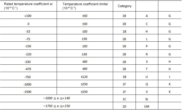
According to the American standard EIA-198-D, the temperature characteristics of ceramic capacitors are represented by three parts using letters or numbers: the first part (e.g., the letter C) represents the significant digits of the temperature coefficient α; the second part represents the multiplier of the significant digits (e.g., 0 represents 10°); and the third part represents the tolerance with respect to temperature change (expressed in×10-6℃-1). The meaning of these letters and numbers is shown in Table 1.
Table 1 Class I Dielectric Temperature Characteristics (EIA-198-D)
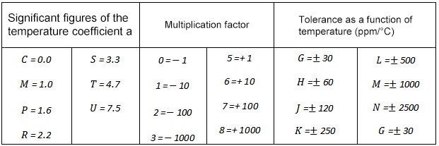
For example, C0G (sometimes also called NPO) indicates: the first letter C represents a significant digit of 0 for the temperature coefficient; the second digit 0 represents a multiplier of 10⁰=1 for the effective temperature coefficient; and the third letter G represents a tolerance of ±30×10⁻⁶℃⁻¹ with respect to temperature change, i.e., (0±30)×10-6℃-1. This notation directly reflects the stability of the performance of ceramic capacitors under temperature changes. C0H is represented as follows: the first letter C indicates that the significant digit of the temperature coefficient is 0, the second digit 0 indicates that the multiplier of the effective temperature coefficient is 100=1, and the third letter H indicates a tolerance of ±60×10-6℃-1 with respect to temperature change, i.e., (0±60)×10-6℃-1 . S2H is represented as follows: the first letter S indicates that the significant digit of the temperature coefficient is 3.3, the second digit 2 indicates that the multiplier of the effective temperature coefficient is 10²=100, and the third letter H indicates a tolerance of ±60×10-6℃-1 with respect to temperature change, i.e., (-330±60)×10-6℃-1.
IEC also has corresponding standards: CECC 32100/IEC-384-8, as shown in Table 2.
Table 2 Temperature Characteristics of Class I Dielectrics (CECC32100/IEC-384-8)
The capacitance of Class I ceramic capacitors hardly changes with temperature. The following example uses C0G dielectric. The variation of the C0G dielectric is only (0±30)×10-6℃-1, and in fact, the capacitance change of C0G with temperature is less than (0±30)×10-6℃-1, approximately half of (0±30)×10-6℃-1, as shown in Figure 1. Over the entire operating temperature range (-55~+125°C), the capacitance change is about 0.3%. This small variation indicates that the C0G dielectric performs excellently in ensuring the performance of ceramic capacitors. Usually, a temperature coefficient of capacitance change of (0±30)×10-6℃-1 is sufficient for most circuits.
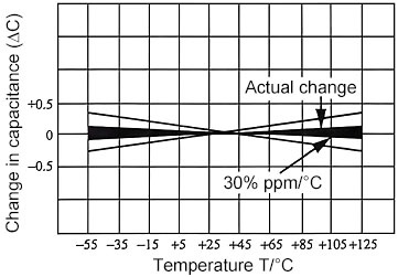
Figure 1 Relationship between Capacitance Change and Temperature
The dissipation factor of Class I ceramic dielectric (such as C0G) capacitors changes very little with temperature, as shown in Figure 2. The dissipation factor is lowest at 40-60℃, approximately 0.9%, and increases at temperatures below or above this range, reaching a maximum of approximately 1.3%.
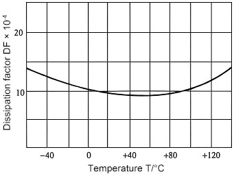
Figure 2: Relationship between Dissipation Factor and Temperature
The insulation resistance of C0G dielectric changes relatively significantly with temperature. The insulation resistance decreases from 10000s (or Ω·F) at -40℃ to slightly over 200s at +125℃. This characteristic is of great importance for evaluating the performance of ceramic capacitors in high and low-temperature environments. Here, the time constant is used to conveniently represent the insulation resistance of C0G dielectric capacitors with various capacitances.
The relationship between the capacitance of C0G dielectric capacitors and frequency is shown in Figure 4. It can be seen that the capacitance of C0G dielectric capacitors is essentially independent of frequency, and XUANSN’s products demonstrate stable and reliable performance in practical applications.
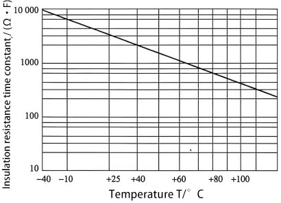
Figure 3: Relationship between Insulation Resistance and Temperature
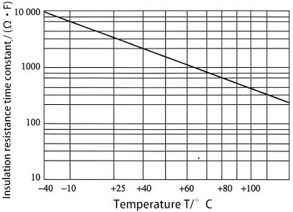
Figure 4: Relationship between Capacitance and Frequency