1 Analysis of Capacitor FailureUnder Climate Influences
1.1. High and Low Range Temperatures
In their respective general descriptions, the high range temperature Tmax and the low range temperature Tmin are defined as the maximum and minimum ambient temperatures at which the capacitor can operate continuously. Exceeding these temperature ranges may induce capacitor failure.
When a capacitor is subjected to ripple current, its surface temperature may rise above the ambient temperature due to heat dissipation.
1.2. Rated Temperature
The rated temperature TR is defined as the maximum ambient temperature at which the rated voltage is continuously input. For polyester and polypropylene film capacitors, the rated temperature is TR = 85℃, while for polystyrene and polyphenylene sulfide film capacitors, it is TR = 105℃.
1.3. Test Reference Temperature
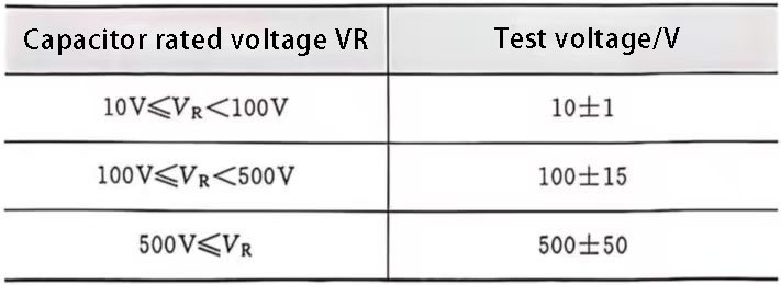
According to IEC 68-1, Supercapacitor Principles, the reference temperature for all electrical tests is defined as 20℃. Test results obtained at other temperatures can be converted to the reference temperature, if necessary. Conversion factors for capacitance and insulation resistance are shown in Table 1.
Table 1 Relationship between Rated Voltage and Test Voltage
1.4. Reference Temperature
Under the reference conditions in the reliability specification, an ambient temperature of 40℃ is defined as the reference temperature per DIN 40039.
1.5. Storage Temperature
All capacitors listed in the datasheet can be stored within the entire storage temperature range of the capacitor.
2 Self-Inductance and Resonance
At high frequencies, the parasitic inductance of a capacitor will cause self-resonance, which can cause unwanted effects during circuit design. If not properly controlled, it may also indirectly increase the risk of capacitor failure. The parasitic inductance of a capacitor is affected by the electrode connection path and winding structure. Capacitors manufactured using a non-inductive method (non-inductive capacitors) all have low inductance. The parasitic inductance of a capacitor typically has a maximum value of 1nH/mm of wire length and capacitor length.
The frequency range of a capacitor’s self-resonance (self-oscillation), a characteristic of capacitor performance, can be seen in Figure 1.
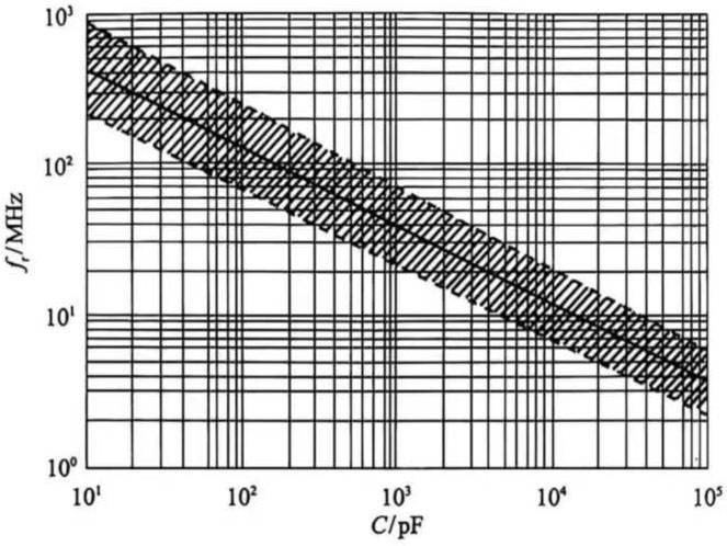
Figure 1 Relationship between Capacitor Self-Resonance Frequency and Capacitance
3 Relationship between Failure Rate and Application Conditions
Failure rate is a key parameter for the quality and reliability of electronic components. In addition to being related to manufacturing quality, it is also significantly affected by application conditions. The factors that primarily influence capacitor failure rates during use are operating temperature and operating voltage. Figures 2 through 6 show the relationships between the failure rates of different dielectric materials and operating temperature and voltage. These curves show the failure rates of paper, polystyrene, polyester, polypropylene, and polyphenylene sulfide capacitors, respectively. The vertical axis represents the failure rate per billion hours, and the horizontal axis represents the operating temperature. The five curves/sloping lines in the figure show the relationships between the failure rates of capacitors at 1.5 times the rated voltage and operating temperature, 1.25 times the rated voltage and operating temperature, 1 times the rated voltage and operating temperature, 0.75 times the rated voltage and operating temperature, and 0.5 times the rated voltage and operating temperature.
First, the failure rate increases with increasing operating temperature. Under rated voltage conditions, the failure rates of Evox-Rifa paper, polystyrene, polyester, polypropylene, and polyphenylene sulfide capacitors increase with increasing temperature, with the per-billion-hour failure rates increasing from 0.2, 1, 3, 2, and 1.5 at 0℃ to 100, 1000, 1000, 1500, and 300 at 105℃, respectively.
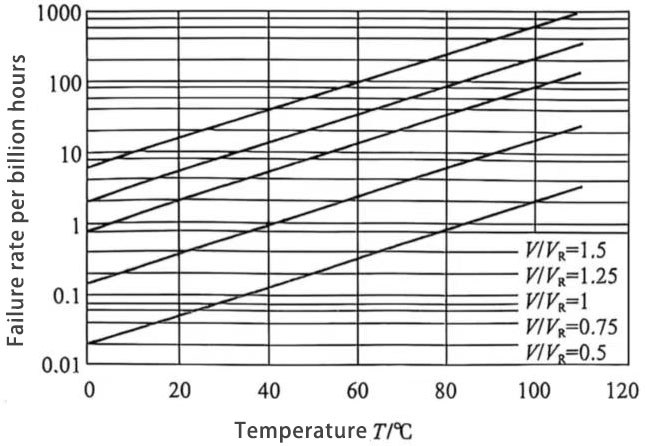
Figure 2: Failure rate of paper capacitors versus temperature
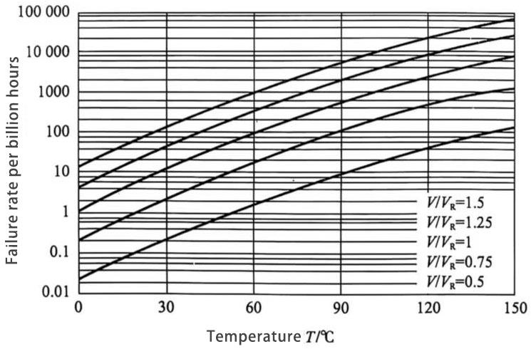
Figure 3: Failure rate of polystyrene capacitors versus temperature
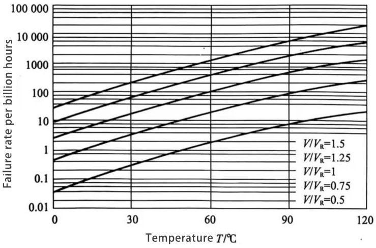
Figure 4: Failure rate of polyester capacitors versus temperature
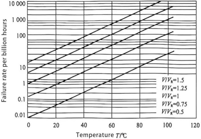
Figure 5: Failure rate of polypropylene capacitors versus temperature
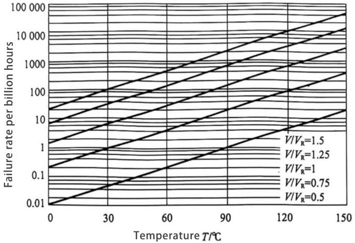
Figure 6: Failure rate of polyphenylene sulfide capacitors versus temperature
At the same operating temperature, an increase in operating voltage will also lead to an increase in the failure rate of capacitors. At room temperature (30℃), the corresponding failure rates per billion hours for operating voltages of 0.5VR, 0.75VR, 1VR, 1.25VR, and 1.5VR are 0.08, 0.6, 3, 8, and 30 for paper capacitors, 0.25, 2.5, 12, 40, and 130 for polystyrene capacitors, 0.4, 4, 20, 80, and 220 for polyester capacitors, 0.1, 1, 6, 20, and 60 for polypropylene capacitors, and 0.05, 1, 7, 30, and 100 for polyphenylene sulfide capacitors.