1 Analysis of filter capacitor overvoltage protection characteristics
The overvoltage research and insulation coordination of AC and DC filters have certain particularities, mainly because a large-capacity capacitor is installed in the filter. For the AC and DC voltage levels used in DC transmission projects, all filter capacitors are installed on the high-voltage side close to the bus. Since capacitors have the functions of withstanding overvoltage and isolating overvoltage, it is generally not necessary to install lightning arresters for overvoltage protection. In addition, the overvoltage generated on the system side is not easy to be transmitted to low-voltage equipment below the capacitor, such as reactors, resistors and current transformers. On the other hand, since these low-voltage devices are directly connected in series with large capacitors, when the two ends of the filter are directly short-circuited, the fully charged high-voltage capacitor will directly discharge the low-voltage equipment, generating overvoltage on the low-voltage equipment, and generating overvoltage problems that need to be focused on for capacitor overvoltage protection on the low-voltage equipment.
As shown in Figure 1, the protection principle diagram of the filter lightning arrester. The filter is a single-tuned filter tuned to the 11th harmonic. Under the pure power frequency voltage Un, the capacitor voltage Uc is 121Un/120, and the reactor voltage UL is Un/120. Therefore, the normal operating voltage of the reactor is very low. When the influence of harmonics is fully considered, the voltage of the reactor is only in the order of several thousand volts. When a short circuit to ground occurs near the filter bus, the capacitor is charged to the protection level of the bus arrester before the short circuit. During the short circuit, this voltage will be directly added to the reactor, causing an overvoltage of steep wave nature. As the capacitor discharges and oscillates, an operating overvoltage will also be generated on the reactor. This operating condition puts forward special requirements for capacitor overvoltage protection.
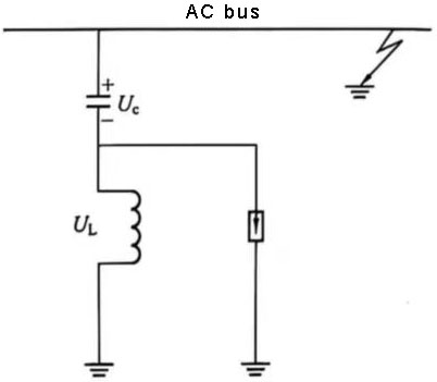
Figure 1 Schematic diagram of filter arrester protection
2 Arrester configuration
The structural types of AC and DC filters are different, and the configuration of their arresters is also different. Two typical filter arrester configurations are shown in Figures 2 and 3 respectively. From the configuration of these two typical filter arresters, it can be seen that the configuration principle of the arrester in the filter is: for high-voltage capacitors, no special arrester is configured; for low-voltage reactors and resistors, an arrester directly connected in parallel with them is configured. This configuration method fully considers the inherent characteristics of capacitor overvoltage protection.
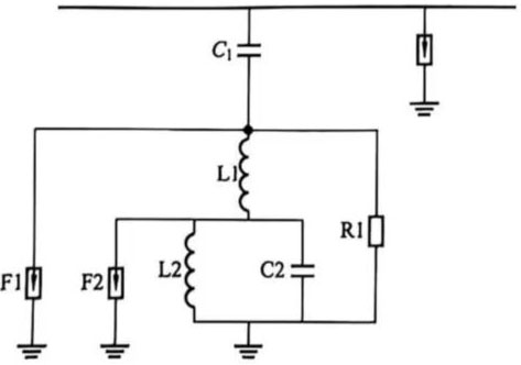
Figure 2 Dual-tuned band high-pass filter arrester configuration
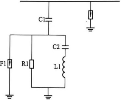
Figure 3 Configuration of low-order C-type filter arrester
After the configuration of the arrester is determined, an important task is to determine the rated voltage of the arrester. As mentioned earlier, the continuous operating voltage of the arrester in the AC and DC filters is very low, only a few thousand volts to tens of kilovolts, while the capacitor connected in series with it may be charged to hundreds of kilovolts. When an external short circuit occurs, the charged capacitor is connected in parallel with the low-voltage reactor, generating dozens of times the expected overvoltage. For this case, the selection of the rated voltage of the arrester cannot be based on the highest continuous operating voltage, but should be based on a principle similar to the selection of the rated voltage of the DC neutral point arrester. The principle of this process can be illustrated by the curve of the relationship between the comprehensive cost of the arrester and equipment and the rated voltage of the arrester shown in Figure 4, where the blank in the low voltage section indicates the rated voltage range that is not allowed to be used due to the limitation of the maximum continuous operating voltage. For different rated voltages of arresters, the energy requirements of the arrester and the insulation requirements of the equipment can be obtained through the overvoltage study described below. From this, the comprehensive cost of the arrester and equipment can be calculated, and the optimal rated voltage of the arrester can be selected through multiple trials.
As can be seen from Figure 4, the curve with a lower cost is generally relatively flat, indicating that the comprehensive cost in this area is not very sensitive to the rated voltage of the arrester. In order to ensure the safety of the equipment, a higher rated voltage should be taken as much as possible without a significant increase in cost. At the same time, it is also helpful to solve the problem of excessive arrester action current when the filter is put into use as described below.
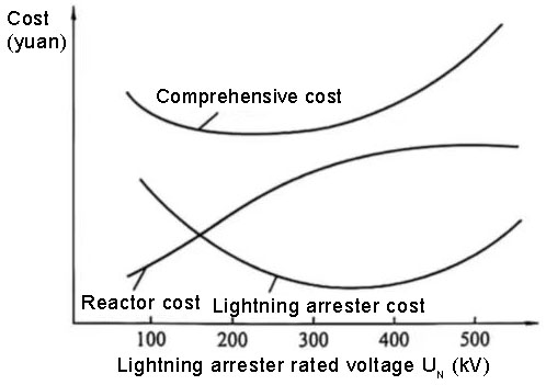
Figure 4 Relationship curve between the comprehensive cost of arresters and equipment and the rated voltage of arresters
The AC filter is different from other electrical equipment in the DC system. It needs to be put into and removed as the DC power changes. For DC transmission projects whose main purpose is to interconnect power grids, an average of two load cycles per day can be considered, that is, most AC filters need to be switched on and off twice a day. At the moment when the AC filter is switched on, the residual voltage of the capacitor (which is zero most of the time, which is determined by the basic condition that the control system must ensure that the capacitor can only be switched on again after a certain period of time after it is withdrawn) may be very different from the instantaneous voltage of the corresponding phase of the bus. This difference will be instantly added to the low-voltage reactor and the lightning arrester connected in parallel with it. If the voltage difference is greater than the arrester action voltage, the lightning arrester will dissipate considerable energy. Because this action is quite frequent, it will have an unignorable impact on the life of the lightning arrester.
3 Capacitor overvoltage protection and overvoltage research
The overvoltage research of AC and DC filter arresters is mainly aimed at the fault type of short circuit of the filter bus to the ground. Since the overvoltage caused by the sudden short circuit has the nature of a steep wave, the circuit model should adopt the steep wave research model. Specifically, the high-voltage capacitor adopts a series model of its own capacitance and stray inductance, and the capacitor itself is charged to the operating wave protection level of the busbar lightning arrester; the reactor is represented by its own inductance in parallel with the stray capacitance plate type: the resistor is represented by its own resistance and stray inductance plate type: the lightning arrester pole type should also consider the characteristics under steep waves: the fault point and the lead are represented by stray inductance together. The schematic diagram of a standard filter overvoltage research model is shown in Figure 5. In the study, the distance between the fault point and the filter is simulated by changing the stray inductance representing the length of the lead, and the most serious overvoltage situation can be searched. . These studies provide a theoretical basis for improving the capacitor overvoltage protection scheme.
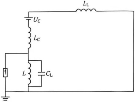
Figure 5 Schematic diagram of filter overvoltage research model
The same model can also be used for overvoltage research when the filter is put into operation. The only difference is that the AC system is represented by equivalent potential and equivalent impedance. By changing the closing phase, the law of the change of arrester energy with the closing phase can be obtained. Combined with the phase statistical characteristics of the switch closing, or intentionally taking measures to control the closing phase, such as using a phase selection and opening control device to control the phase, according to the switching frequency of twice a day, it is submitted to the equipment manufacturer for arrester design.
4 Insulation coordination
The insulation coordination of AC and DC filters is mainly divided into two parts.
(1) The first part is the high-voltage capacitor, which includes three aspects: ① The insulation level of the high-voltage side of the capacitor is considered according to the AC busbar equipment; ② The insulation level of the low-voltage side of the capacitor is considered according to the insulation level of the high-voltage side of the reactor directly connected in series; ③ The insulation between the two ends of the capacitor can be considered according to the sum of the protection level of the busbar arrester and the protection level of the arrester connected to its low-voltage side, and then the insulation requirements are determined according to the insulation margin of the general air insulation equipment. This insulation requirement only affects the structure of the capacitor stack, and the internal stress of the capacitor is mainly determined by the steady-state working condition. In the design of capacitor overvoltage protection, these factors need to be considered comprehensively.
(2) The second part is low-voltage equipment. The insulation coordination is carried out according to the protection level of the filter arrester, and the insulation margin is selected according to the air insulation equipment. It should be emphasized that when considering the protection level of the filter arrester, its lightning wave coordination current cannot be as large as the AC switch field arrester, such as 20kA for the 500kV switch field. Instead, a much smaller coordination current should be used, with a typical value of 2kA. Otherwise, not only will the production cost of the arrester be significantly increased, but the insulation level of the equipment will be controlled by the lightning wave overvoltage, which significantly increases the insulation level requirements.