1 Circuit breaker operation overvoltage and inrush current
The task of the capacitor circuit breaker is to close and close the load current and break the short-circuit fault current to protect the electrical equipment in the circuit from damage. The circuit breaker will generate overvoltage when performing these closing and opening operations. The amplitude of the operating overvoltage is closely related to the parameters of the power system, especially the circuit breaker characteristics and the phase angle when opening and breaking. The overvoltage multiple caused by closing at an unfavorable phase angle is very large, which will endanger the stability of the power system and interfere with the normal operation of highly sensitive electrical equipment in the circuit or nearby circuits. The method of limiting overvoltage is as described in the previous section. Lightning arresters can be installed, and the frequent operation of lightning arresters under operating overvoltage will greatly shorten its life (this is just as the inspection personnel of the converter station often find that the lightning arrester installed in the filter field will sometimes find the operation of the lightning arrester action counter after the filter switching operation).
The AC filter group is mainly composed of large-capacity capacitors and reactors. For unloaded capacitors, closing the circuit breaker at any point will generate very high inrush current and operating overvoltage, especially at voltage peaks. The situation is even more serious when operating parallel capacitor banks, and higher operating overvoltages will be generated due to reflections from the power system network terminals.
At the moment when the capacitor bank is first closed and put into operation, the capacitor is in an uncharged state, and the current flowing into the capacitor is only limited by the system impedance. Since the system impedance is very small, it is close to a short-circuit state, and a large closing inrush current will be generated at this time, flowing into the capacitor. If the circuit breaker is closed at the voltage peak, the largest inrush current will be generated on the capacitor.
When one or more groups of capacitors are already in operation on the busbar of the converter station system, when another group of capacitors is put into operation, an additional closing inrush current will be generated at the moment of closing. Since the distance between the additional capacitor group and the operating capacitor group is very close, the inductance between them is very small, almost zero. The additional capacitor is similar to the short-circuit state, so the operating capacitor group will charge the additional capacitor in large quantities, and the entire impact closing inrush current will flow into the additional capacitor group, causing the inrush current to reach a dangerous level. Therefore, in actual operation, it is necessary to effectively limit it by reasonably configuring capacitor circuit breaker and control strategies.
2 Circuit breaker phase selection and opening technology
2.1 Development of phase selection and opening technology
Since the mid-1970s, foreign countries have begun to study the technology of phase selection and opening control of high-voltage circuit breakers. The design idea is to calculate the circuit breaker to close or open at a fixed phase, so as to minimize the operating overvoltage and surge current amplitude in the system. Before the 1990s, due to the limitations of the development of circuit breakers and controllers, this technology has always remained in theoretical research. In the 1990s, the continuous improvement of high-voltage circuit breaker manufacturing level, microprocessor technology, microelectronics technology, measurement and control technology, and the improvement of users’ requirements for power supply quality have made circuit breaker phase selection control technology rapidly move towards practical use since the mid-1990s, which is reflected in the rapid increase in the use of phase selection control circuit breakers in Europe and the United States. Although my country has also conducted research on this advanced technology, there was no example of practical application as of 1998.
In recent years, with the development of electronic technology, this technology has received more attention from both the international and domestic parties. In 1998, a phase control unit was used in the circuit breaker of a transmission line in my country to replace the closing resistor to limit the closing overvoltage of the line. At the end of 2000, two more phase control units were put into operation to limit the opening overvoltage of the shunt reactor. By the end of 2001, seven phase control units were put into operation, and two phase control units were first used in SF6 circuit breakers in shunt capacitor circuits in my country. After 2005, SF6 circuit breakers with phase selection and opening technology were gradually used in AC filters and shunt capacitors in new ultra-high voltage and ultra-high voltage DC converter stations in China.
2.2 Application prerequisites of phase selection and opening technology
The phase selection and opening control circuit breaker consists of a phase control device and a high-voltage circuit breaker. Whether the phase-selective control circuit breaker can achieve the effect of suppressing overvoltage and surge current depends on the accuracy of the operation time (i.e. the accuracy of the phase when closing and opening). The required capacitor circuit breaker needs to meet the following two conditions:
(1) The dispersion of the closing and opening operations of the circuit breaker should be small. In order to realize the phase-selective operation, the performance of the circuit breaker’s operating mechanism should be stable to reduce the dispersion of each operation and obtain the accurate closing or opening phase. The error of each closing and opening time must be within ±0.5ms.
(2) The circuit breaker should have three-pole independent operation. Because the three phases of the power supply (i.e. A, B, and C phases) differ by 120° in phase, in order to realize the three-phase phase-selective operation, each phase of the circuit breaker must be equipped with an independent operating mechanism. For example, when the filter three-phase circuit breaker is closed, since the three-phase voltage phases differ from each other, in order to avoid the three-phase surge current, each phase must be independently selected when closing.
2.3 Application of phase selection and opening technology in filters and parallel capacitors
(1) Basic principles of application. By analyzing the transient overvoltage when single-phase filters and parallel capacitors are combined, opened and disconnected, it can be seen that: when closing, the smaller the phase of the voltage, the smaller the voltage on the contact. In this way, when closing at the voltage zero point, the overvoltage and surge current produced are smaller; when opening, the contacts are separated, the smaller the phase of the current, the greater the distance the contacts are separated when the current passes zero, the higher the dielectric strength, and it is not easy to re-ignite and re-breakdown. The arc gap will not generate overvoltage after the current passes zero. Therefore, when the filter and parallel capacitor are combined and opened, the phase selection and opening control device can be used to minimize the overvoltage and surge current generated after the capacitor circuit breaker contacts are closed and opened.
When the filter and parallel capacitor are closed, in order to reduce the inrush current and operating overvoltage, the three-phase closing is closed at the voltage zero crossing point in the order of L1-L3-L2, with a time difference of 1/6 cycle (i.e. 3.3ms), and three voltage zero crossings appear continuously within 1/3 cycle. When the filter and parallel capacitor are opened, in order to reduce the operating overvoltage as much as possible, the three-phase opening is opened at the negative peak of the voltage in the order of L1-L2-L3, with a time interval of 1/3 cycle (i.e. 6.7ms). If the three-phase circuit breaker selects the appropriate opening and closing time points when operating in phase, the generation of inrush current and operating overvoltage can be reduced from the root.
(2) Application example of phase selection and opening technology in filter. The typical wiring schematic diagram of phase selection and opening control is shown in Figure 1. The following is an introduction using closing as an example. After the controller receives the closing command from the DC control protection system, it saves the signal and does not issue it for the time being. At the next appropriate voltage phase, the closing command is sent to the closing coil of the circuit breaker to achieve the closing action of the circuit breaker at the appropriate voltage phase, ensuring the shortest transient time during closing and the smallest transient impact on the equipment.
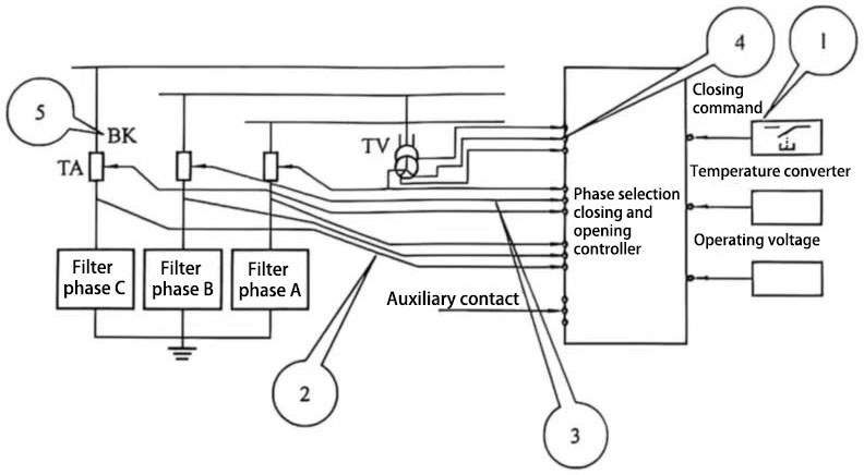
Figure 1 Typical wiring diagram of phase selection closing and opening control
1-switch input terminal (receives closing and opening commands sent by the DC control protection system); 2-filter (shunt capacitor) incoming line side current transformer; 3-phase selection closing and opening controller closing and opening command output terminal (directly connected to the circuit breaker closing and opening coil); 4-filter bus voltage transformer on the circuit breaker power supply side (provides reference voltage for the device); 5-filter (shunt capacitor) operating circuit breaker
When the closing (opening) command is received at the input terminal 1 in the figure, the internal microprocessor of the phase selection control device starts timing when the reference voltage passes through zero (if it is a closing command), and after a certain time TVTOT (total waiting time), sends a command to the circuit breaker action coil. TVTOT is mainly determined by the initial setting data on site and the previous closing and opening data. If the control is to be more precise, TVTOT intelligent compensation can be performed according to the changes in the external temperature or other external parameters collected by the temperature transmitter.
1) Closing sequence. The closing sequence of the circuit breaker under the control of the phase selection closing device is shown in Figure 2.
For the AC filter and the parallel capacitor group, the impact current is minimized when the power supply reference voltage passes through the zero point, and the impact on the capacitor and the system is also minimized. Therefore, in the waveform diagram shown in Figure 2, the circuit breakers of the corresponding phases should be closed when the reference voltages of the three phases A, B, and C pass through the zero point. If the circuit breaker of phase A is closed, to ensure that the three-phase closing is completed in the shortest time, it must be closed in the order of A-C-B. In Figure 2, curve 1 is the reference voltage of phase A; the first half of curves 2, 3 and 4 is the voltage ug on both sides of the circuit breaker before the closing of the capacitor circuit breaker of phase A, B, and C, and the second half is the phase current i after closing; curve ubd represents the dielectric strength between the moving and static contacts of the circuit breaker.
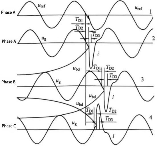
Figure 2 Closing sequence of the circuit breaker under the control of the phase selection closing device
In fact, the closing process of the circuit breaker can be divided into three time periods, namely TD1, TD2 and TD3 shown in Figure 2. For my country’s 50Hz AC power grid, if the A-phase circuit breaker receives the closing command signal at time 0, then the B-phase should receive the signal after 6.7ms, and the C-phase should receive the closing command signal after 3.3ms, that is, the A-phase TD1=0ms, the B-phase TD1=6.7ms, and the C-phase TD1=3.3ms. The time interval from the circuit breaker receiving the closing command to the dielectric breakdown between the moving and static contacts is defined as TD2, and the time interval from the dielectric breakdown between the moving and static contacts to the complete contact of the moving and static contacts (closing is completed) is defined as TD3. Although the values of TD2 and TD3 are very small, these two parameters cannot be ignored in order to accurately control the closing angle of the circuit breaker. At present, the various phase selection closing and opening devices of different manufacturers in operation in China must consider this factor in order to achieve accurate control of the closing angle of the circuit breaker.
2) Opening sequence. For capacitive loads such as filters and parallel capacitors, the best time to open the circuit is at the negative peak of the voltage. Usually, the opening process of the circuit breaker can also be divided into two time periods TD1 and TD2, where TD1 is the time interval from the zero-crossing point of the reference voltage to the next current zero-crossing point of the corresponding phase. For a 50Hz power grid, if the A-phase voltage is used as the reference voltage, in the case of pure capacitive load, the TD1 of phase A is 5ms (corresponding to a phase of 90°), the TD1 of phase B is 11.7ms (5ms+6.7ms corresponding to a phase of 210°), and the TD1 of phase C is 18.4ms (5ms+6.7ms+6.7ms). TD2 is the time interval from when the circuit breaker receives the opening command to when the circuit breaker is completely disconnected.
2.4 Debugging of Phase Selection and Disconnection Devices
Phase selection and disconnection control has different correction and compensation parameters for different environments and different circuit breakers (which is determined by the dispersion of circuit breaker action). Phase selection and disconnection controllers that have not been subjected to field performance tests effectively reduce inrush current and overvoltage when switching capacitor circuit breaker. However, a sufficiently strong inrush current or overvoltage shock is enough to cause damage to capacitors. Therefore, field debugging of phase selection and disconnection control devices is crucial to their function.
The following uses the Switchsync F236 phase selection and disconnection controller produced by ABB to switch capacitors as an example to illustrate the debugging process of such equipment.
(1) Preparation before debugging. Due to the dispersion of different circuit breaker actions, even the same circuit breaker has slight differences in each action time. The circuit breakers used to operate filters and shunt capacitors in DC converter stations are all three-phase split circuit breakers, so the circuit breaker action times between different phases are also different (different mechanisms, internal and external environments can determine the existence of such differences). The action time of the circuit breaker is an important factor affecting the control closing and opening accuracy. Therefore, before debugging the F236 device, the closing time Tbt and opening time Tbf of each phase circuit breaker should be measured as accurately as possible. In places with large temperature differences, the influence of temperature on the closing and opening time of the circuit breaker should also be considered, otherwise it may cause the TD2 time deviation to be too large, and the purpose of closing and opening at the appropriate phase is not achieved (this requires special attention from the commissioning personnel, because the DC converter station switches the filter at any time, and it may even happen that the DC system power is increased or decreased during the day and night when the temperature difference is the largest, resulting in the switching of the filter and the shunt capacitor). Measure the changes in the opening and closing time of the circuit breaker at different temperatures to correct the circuit breaker action time. The data usually measured is realized by inputting the following parameters into the phase selection controller.
1) Tbt: measured closing time of circuit breaker;
2) Tbf: measured opening time of circuit breaker;
3) Te: measured external ambient temperature of circuit breaker;
4) A: measured external parameters of circuit breaker;
5)Tk1: compensation time of circuit breaker closing under different external ambient temperatures;
6) Tk2: compensation time of circuit breaker closing under different external parameters;
7) Tk3: compensation time of circuit breaker opening under different external parameters;
8) TB = Tbt-Tk1-Tk2: compensation-corrected closing time;
9) TB = Tbf-Tk3: compensation-corrected opening time.
(2) F236 internal parameter setting. The main internal parameters of F236 are as follows.
1) Function variable Duty: When Duty=1, it means that the device only controls the closing operation of the circuit breaker; when Duty=2, it means that the device only controls the opening operation of the circuit breaker; when Duty=3, it means that the device can control the opening and closing operations of the circuit breaker at the same time.
2) Closing time of circuit breaker: Enter the corrected closing time Tbt of the A-phase capacitor circuit breaker
3) Opening time of circuit breaker: Enter the corrected opening time Tbf of the A-phase circuit breaker
4) Closing delay 1: Since my country’s power grid is 50Hz, the following parameters are selected: A-phase TD1=0ms, B-phase TD1=6.7ms, C-phase TD1=3.3ms.
5) Opening delay 1: A phase TD1 = 0ms, B phase TD1 = 11.7ms, C phase TD1 = 18.4ms.6) Closing delay 2 and closing delay 3: If the F236 device is used with a specific switch, and this specific switch has a very mature field case, this closing delay 2 and closing delay 3 can be based on the value provided by the equipment manufacturer or the field experience value, but it needs to be verified again during commissioning.
7) Opening delay 2: Usually TD2 for each phase = 8.2-δt (ms), where δt is the difference between the operating time of the B and C phase circuit breakers and the A phase circuit breaker.
(3) Circuit breaker live closing and opening test. The test data of the circuit breaker with power on and off are shown in Table 1.
Table 1 Test data of the circuit breaker with power on
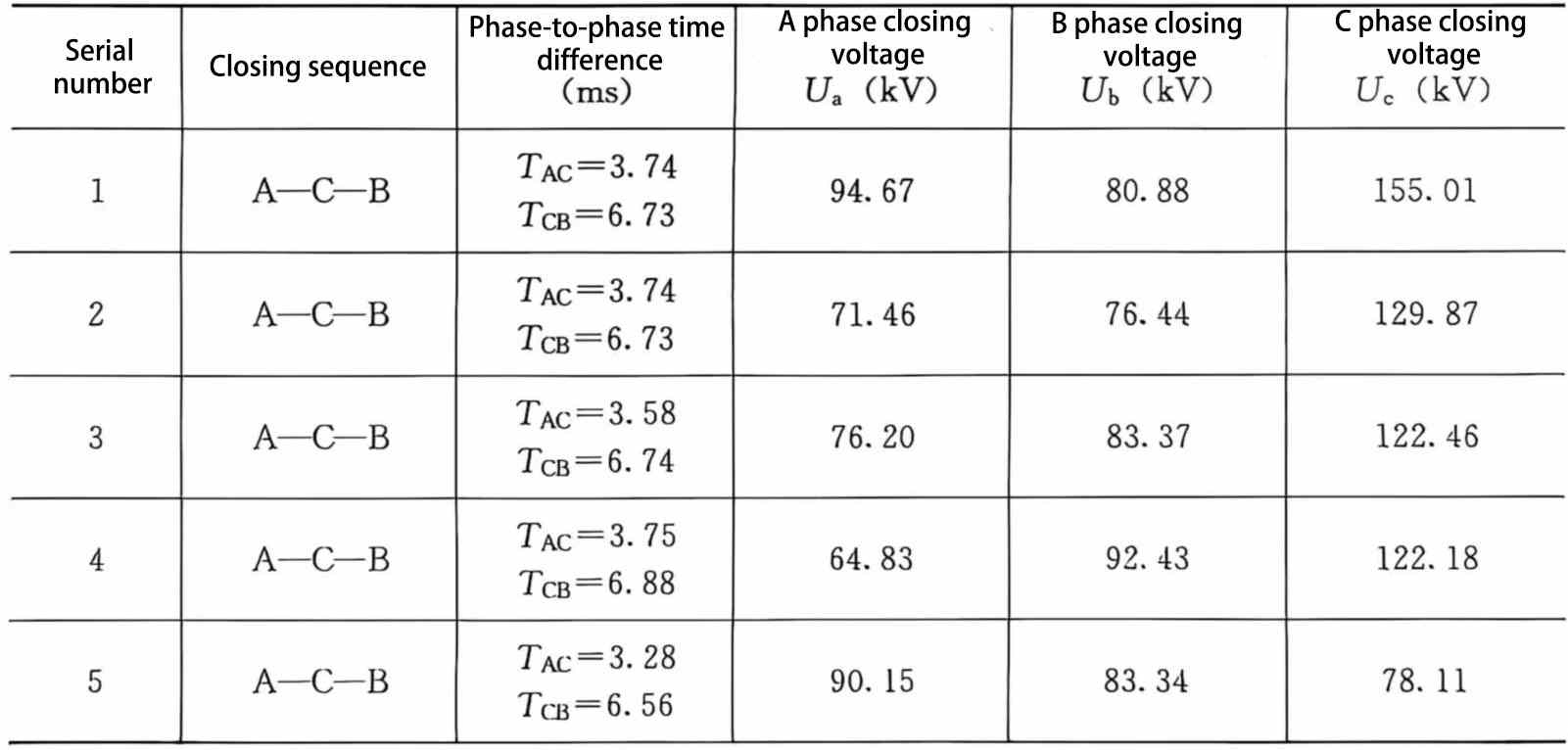
Since the F236 device needs a certain amount of time to detect the reference voltage and the zero-crossing point of the circuit breaker current, it also takes time for the F236 to issue a command and the circuit breaker to operate, which causes a certain difference between the actual closing and opening positions of the capacitor circuit breaker and the expected closing and opening positions. The F236 device has an adaptive mode inside. In the adaptive mode, the device first finds the difference between the actual operation time and the expected operation time, and compensates for half of the difference in the next operation. Table 1 records the data of the first five closings of the circuit breaker on site. Figure 3 shows the waveform of the fifth closing of the circuit breaker. It can be seen from the figure that the instantaneous values of the three-phase voltages of the circuit breaker at the moment of the fifth closing are all less than 100kV, and the phase-to-phase time difference also meets the condition of (3.3±0.4)ms, meeting the control requirements.
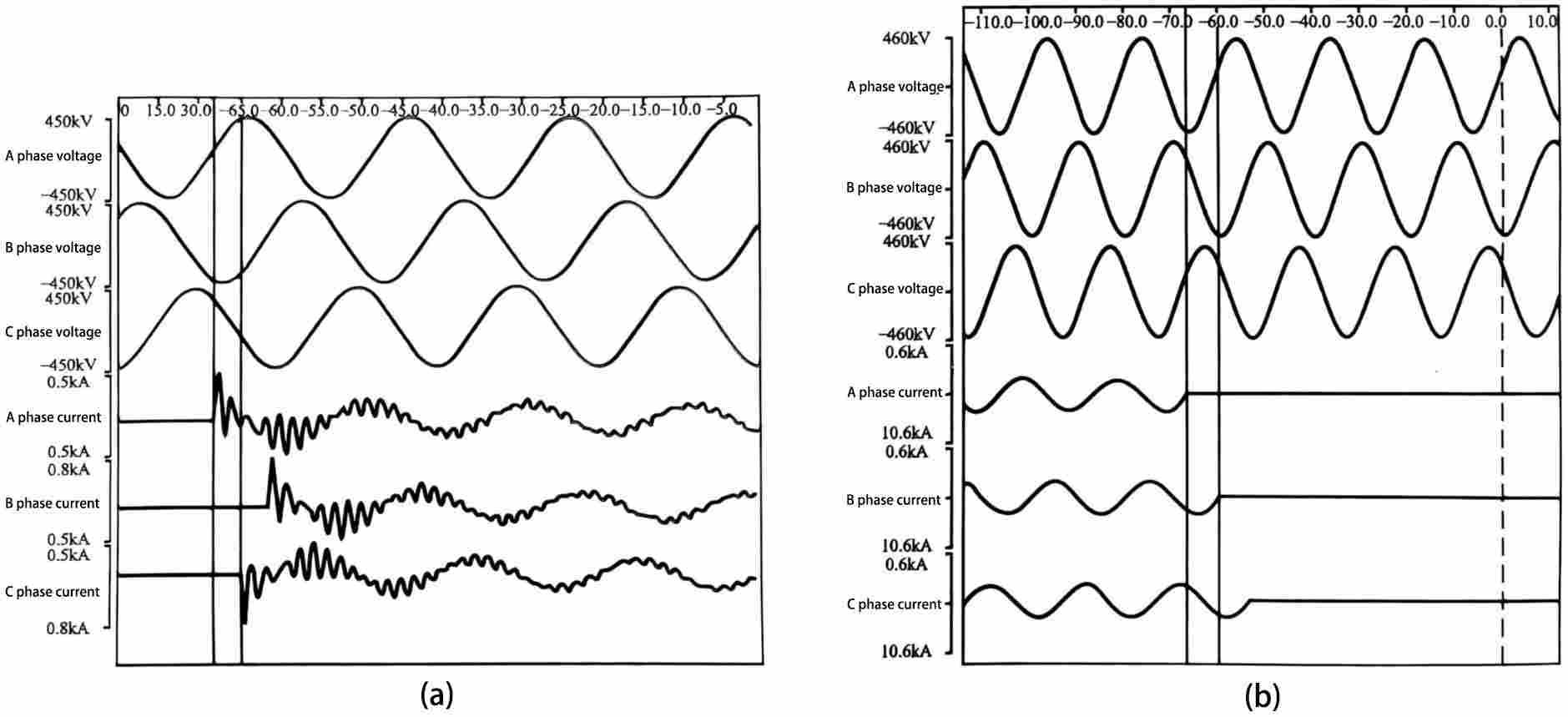
Figure 3 Recording of the fifth closing of the circuit breaker (a) Closing process; (b) Opening process
2.5 Specific application and current status of phase selection and opening technology
(1) Application. After 2005, phase selection and opening technology has been widely used in newly commissioned converter stations in my country. The use of circuit breakers with phase selection and opening technology has become an important means to limit the overvoltage and inrush current of filters and parallel capacitors. As shown in Table 2, the current use of capacitor circuit breaker phase selection and opening devices in some domestic converter stations.
Table 2 Use of circuit breaker phase selection and opening devices in some domestic converter stations
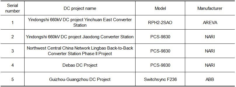
(2) Current status of localization development. Domestic circuit breaker manufacturer Pinggao Group High Voltage Switch Factory and Nanrui Relay Protection have jointly developed the PCS-9830 series circuit breaker phase selection and opening device, which has been used in many domestic DC transmission projects. The waveform diagram of phase selection and opening of the device is shown in Figure 4.
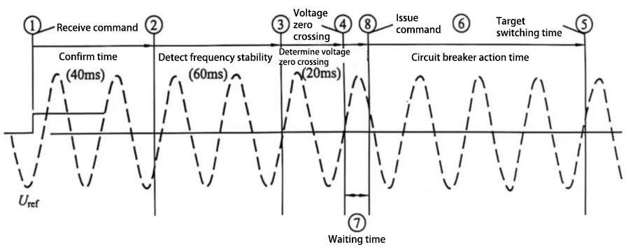
Figure 4 Waveform diagram of phase closing and opening selected by PCS-9830 device
The PCS-9830 device collects bus TV voltage in real time, randomly receives three-phase closing and opening commands from measurement and control, and delays the issuance of phase closing and opening commands at the appropriate voltage phase. This phase-splitting command enters the phase closing and opening input terminals of the circuit breaker operation box, and is directly connected to the circuit breaker closing and opening coils after the holding circuit.
Considering the inherent action time and secondary circuit delay of the circuit breaker mechanism in different environments, the current or position recovery function can be put into use, so that the capacitor circuit breaker can always perform actual closing and opening operations at the predetermined phase, effectively avoiding transient overvoltage and overcurrent caused by random opening and closing, thereby improving the power quality, protecting the circuit breaker contacts and other electrical equipment, minimizing the impact, and effectively extending the life and maintenance cycle of power equipment.