1 Filters and parallel capacitor overvoltage analysis question
During the operation of the DC transmission system, the DC power will change. The DC transmission system can adjust the transmission power at any time through the control system, which is a great advantage of the DC transmission system. However, in the process of DC system power regulation, after all, accompanied by the switching process of AC filter and shunt capacitor device, there will be two problems when switching these reactive devices: ① a large inrush current is generated when it is put into use; ② overvoltage is generated due to the reignition of the circuit breaker when it is cut off. Therefore, capacitor overvoltage analysis is of great significance in the DC transmission system. Especially for large-scale DC transmission projects used for large coal-fired power and large hydropower, power regulation occurs at any time within a day, within a period of time, and throughout the year. Its frequent operation characteristics make the filter and capacitor tripping caused by overvoltage occur from time to time, especially some early capacitor products produced by domestic capacitor manufacturers for DC systems. In the frequent switching of capacitors, capacitor failures and breakdowns often occur, causing tripping events. In addition to the overvoltage caused by frequent switching of AC filters and parallel capacitors, overvoltage hazards will also occur in some fault conditions, such as: the low-voltage position equipment of the filter is directly connected in series with the large capacitor. When the two ends of the filter are directly short-circuited, the fully charged high-voltage capacitor will directly discharge to the low-voltage equipment, generating overvoltage on the low-voltage equipment. Therefore, it is very important to limit the overvoltage of the filter and parallel capacitor under various normal working conditions and fault conditions to ensure the safe and stable operation of the system. So far, the main solutions are: ① Select a circuit breaker with good performance, that is, a circuit breaker with a low probability of heavy breakdown ② Select a zinc oxide lightning arrester with appropriate configuration; ③ Use a phase selection closing device. However, in actual operation, there are still many problems caused by the unsatisfactory overvoltage limitation during the switching process due to problems with the circuit breaker itself, phase selection problems of the phase selection closing device, or lightning arrester design problems. Therefore, the capacitor overvoltage analysis still requires us to spend energy on equipment selection, operation and maintenance, and testing to take it seriously, and first ensure that the equipment that limits the overvoltage does not have problems.
The overvoltages under the above-mentioned fault conditions are a minority, and more are the operating overvoltages caused by frequent operations or switching that are unique to the DC transmission system.
Due to the presence of inductance and capacitance energy storage elements in the filter and shunt capacitor, energy is released at the moment of circuit breaker operation, generating electromagnetic oscillation in the circuit and causing operating overvoltage. When switching on and off the filter and shunt capacitor group, the inductance-capacitance loop may oscillate, thereby generating operating overvoltage. Especially during the disconnection process, if the circuit breaker has an arc reignition (the low reignition SF6 circuit breaker currently used in the filter and shunt capacitor in the domestic high-voltage DC transmission system basically eliminates the overvoltage caused by the reopening of the circuit breaker during the opening process. According to the characteristics of the circuit breaker products selected for the DC converter station filter and shunt capacitor, this article does not discuss the reignition overvoltage caused by the opening of the circuit breaker), it will cause strong electromagnetic oscillation and higher overvoltage. This overvoltage value is related to the size of the capacitor to be cut and the bus side capacitor.
The following sections mainly introduce the closing operation overvoltage generated by the AC filter and shunt capacitor group when they are put into operation. This overvoltage is mainly the asynchronous (circuit breaker closes at different times) closing overvoltage and the contact bounce overvoltage during closing.
2 Overvoltage Problems of Closing Filters and Shunt Capacitors
The high-voltage circuit breakers used for AC filters and shunt capacitors in DC converter stations are usually SF6 circuit breakers with hydraulic mechanisms or SF6 circuit breakers with spring mechanisms. The circuit breakers have excellent performance in all aspects. When analyzing capacitor overvoltage, assuming that the closing of the three-phase contacts of the high-voltage circuit breaker is synchronous, and the capacitance and inductance values between the capacitors of each phase are also the same, the three-phase closing circuit can be theoretically analyzed according to the single-phase circuit shown in Figure 1.
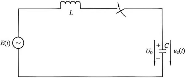
Figure 1 Single-phase Closing Circuit Diagram of Capacitor
Usually, the tail end of the AC filter and shunt capacitor of the converter station adopts star connection. Here, taking star connection as an example, the overvoltage formed by the capacitor group is approximately analyzed. In Figure 1, L is the leakage inductance of the power supply and U0 is the residual voltage of the compensation capacitor C. If the power supply electromotive force Em(t)=Emcosωt, the circuit loss resistance is ignored. The voltage uc(t) on the capacitor C after the circuit breaker is closed is shown in formula (1):
![]() (1)
(1)
The expression of UCm in the above formula is shown in formula (2):
![]() (2)
(2)
UCm in formula (1) and formula (2) is the steady-state voltage amplitude of the capacitor;
ω0-circuit self-oscillation angular frequency, ![]() ;
;
U0-residual voltage on the capacitor C before closing.
When ωL≫ω, UCm=Em.
When the power supply voltage at the moment of closing is exactly the maximum value Em, the capacitor overvoltage analysis shows that the overvoltage is the highest. In order to simplify the calculation, the maximum value of uc UCm is assumed to appear at ω0t=π. Since ω0》ω, at this time ωt≈0, from formula (2):
![]() (3)
(3)
From formula (3), it can be seen that when the high-voltage circuit breaker closes the capacitor group, the maximum value of uc, UCm, is related to the phase angle of the power supply voltage at the moment of closing and the residual voltage U0 on the capacitor, as shown in formula (4):
![]() (4)
(4)
Because both the filter and the shunt capacitor device are generally equipped with a reactor coil on the low-voltage side (some DC converter stations have no tail reactor on the low-voltage side of the shunt capacitor), the residual voltage on the filter and shunt capacitor device should be reduced to a very low level after being disconnected from the system power supply for 5s. Therefore, when the circuit breaker is closed, as long as the time interval from the last disconnection operation is greater than tens of seconds, it can be considered that the residual voltage U0 on the capacitor is ≈0. At this time, the highest overvoltage on the capacitor is
![]() (5)
(5)
If U0 and Em have the same polarity, then UCm is less than 2Em, that is, the overvoltage is less than twice; on the contrary, if U0 and Em have opposite polarities, an overvoltage greater than twice may occur. In general, after the filter and shunt capacitors used in the DC converter station are disconnected from the power supply, each capacitor has a self-discharge circuit, and the DC control protection system will also set the next time the capacitors are put into operation. During this time period, U0≈0 before closing will be satisfied, and the maximum overvoltage after closing is 2Em. When there is a reverse polarity residual voltage on the capacitor C, such as U0=-Em, the maximum value of uc(t) can reach 3Em, see formula (6):
![]() (6)
(6)
It is generally believed that when the filter and shunt capacitors are randomly put into operation when the circuit breaker is not equipped with a phase selection closing device, the closing overvoltage does not exceed twice. Of course, these are to exclude the phenomenon of bouncing due to poor performance of some circuit breakers. For high-voltage DC converter stations, high-voltage circuit breakers generally do not bounce (i.e., when the circuit breaker is connected, the overvoltage will not exceed 2 times). Therefore, capacitor overvoltage analysis can provide a theoretical basis for system design and operation to ensure the safety and stability of equipment.