1 Temperature characteristics of capacitance
🍏Are the parameters of aluminum electrolytic capacitors affected by the application environment?Capacitance varies with temperature. The change itself is determined by the rated voltage and capacitor size, from 25°C to the high temperature limit, the capacitance increase is generally not more than 10%. For the lowest rated temperature of -40℃, the capacitance of low-voltage capacitors typically drops by 20% at -40℃, and the capacitance of high-voltage capacitors drops to 40%. Most drops are less than 10% at -40°C and less than 20% at -55°C. The relationship between the capacitance and temperature of aluminum electrolytic capacitors with different rated voltages of EPCOS is shown in Figure 5.7.
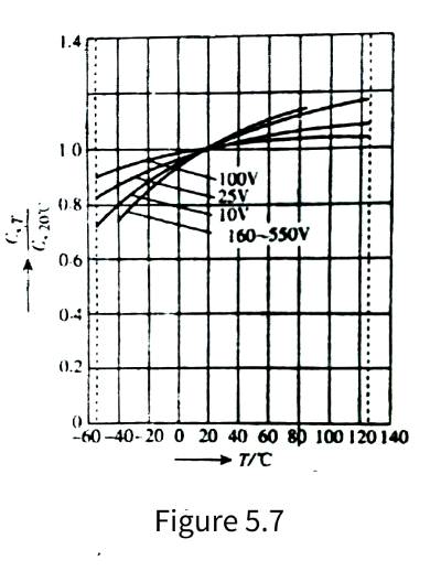
🍎As can be seen from the figure, the characteristic curve is steeper at lower rated voltages, which is usually the result of rougher corrosion (deep corrosion) to increase the anode surface area. Of course, it is also possible to apply a special electrolyte (the viscosity of the electrolyte changes less with temperature) to obtain a capacitance with a small temperature change, so that the capacitor can work in a wide range below 0 °C with little change in capacitance. It makes sense in special applications.
2 The relationship between capacitance and frequency
🍐The effective capacitance of an aluminum electrolytic capacitor decreases with increasing frequency, as shown in Figure 5.8.
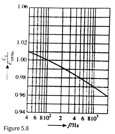
🍊The reasons are as follows: One is a general view. Due to dielectric absorption and loss factor, this concept is undoubtedly correct in film capacitors with dielectric loss as the main loss, but in aluminum electrolytic capacitors, the loss is the loss caused by the resistance of the electrolyte of the electrode itself, and the frequency characteristics of alumina It’s never that bad. Therefore, the characteristic that the capacitance of aluminum electrolytic capacitors decreases with the increase of frequency should not be a problem of dielectric loss, so where is the problem? My opinion is: because aluminum electrolytic capacitors increase the surface area of electrodes, the anode/cathode is The aluminum foil is corroded very rough, so that the rough depth corresponds to the cathode of the electrolyte. Due to the high resistivity of the electrolyte, the capacitor from the depth of the rough anode electrode to the terminal has actually become an RC circuit. As the frequency increases, the effect of this sub-capacitor becomes weaker and smaller, and the equivalent capacitance becomes smaller and smaller. This is the real reason why the capacitance of the aluminum electrolytic capacitor decreases as the frequency increases.
🍋Since aluminum electrolytic capacitors are mainly used in applications that are not sensitive to changes in capacitance, such as rectification, filtering, bypass, etc., changes in capacitance of aluminum electrolytic capacitors with temperature and frequency have little effect on the application. Therefore, the relationship between the capacitance of aluminum electrolytic capacitors, temperature and frequency can be ignored in practical applications.
3 The relationship between leakage current and application environment
🍌Leakage current is one of the biggest damages to aluminum electrolytic capacitors, because leakage current will consume electrolyte, resulting in premature drying and failure of aluminum electrolytic capacitors. Therefore, special attention should be paid to leakage current problems.
3.1 Long-term placement will increase the leakage current of aluminum electrolytic capacitors and solutions
🍉It should be noted that when aluminum electrolytic capacitors are stored in a voltage-free state for a long time without any application, the chloride ions in the electrolyte will damage the alumina dielectric film the most, especially when stored under high temperature conditions, from There is no leakage current flowing from the oxide layer to the anode, and the oxide layer cannot be regenerated. As a result, when the voltage is connected after long-term storage, a leakage current higher than the normal value will be generated. However, as the oxide layer is regenerated during use, the leakage current will gradually decrease to a normal value. At the same time, due to the galvanic cell effect of iron and copper ions, the leakage current of aluminum electrolytic capacitors needs a long time to apply voltage to recover. This process is called aging or energization, and it is usually best to energize aluminum electrolytic capacitors before they are used.
🍇When the aluminum electrolytic capacitor is stored in a voltage-free state, it needs to be energized before the application of ordinary domestic manufacturers for 1 year or foreign famous manufacturers for more than 2 years.
🍓If the long-term aluminum electrolytic capacitor is not energized, the leakage current value may be as high as 100 times its normal value when the power is first turned on. Whether the capacitor can withstand this high initial leakage current is a question when the capacitor is stored for more than 2 years. Therefore, before the aluminum electrolytic capacitor is installed in the circuit. It is best to implement an energizing procedure for aluminum electrolytic capacitors. In addition, when the circuit with capacitors has reached or exceeded the storage life, the capacitors should be operated without load for one hour in a no-load state to prevent excessive leakage current and ripple current from overheating the aluminum electrolytic capacitor. The “explosion” accident occurred, and the leakage current of the capacitor was restored. From this, it can be seen that, for circuits with aluminum electrolytic capacitors, power should be applied for several hours per year during storage. In order to ensure the performance of aluminum electrolytic capacitors in the circuit during continuous storage.
🍈It is undeniable that well-sealed aluminum electrolytic capacitors can even be stored for up to 15 years without any performance loss. If the aluminum electrolytic capacitor does not exceed the storage time, the capacitor can be directly applied to the rated voltage after being taken out of the library. In this case, the enabling process may not be required.
3.2 Voltage characteristics of leakage current
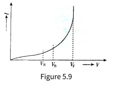
🍒In the data sheet, the leakage current test conditions for aluminum electrolytic capacitors are: the voltage is the rated voltage, and the temperature is the maximum operating temperature. At different voltages, the leakage current of an aluminum electrolytic capacitor varies with the applied voltage, as shown in Figure 5.9.
 w
w
🍑In the figure, VR is the rated voltage of the aluminum electrolytic capacitor, Vs is the surge voltage, and VF is the anodized tempering voltage (breakdown voltage). It can be seen from the figure that VF>Vs>VR, the leakage current of the aluminum electrolytic capacitor increases with the rise of the terminal voltage of the electrolytic capacitor. When the terminal voltage exceeds the rated voltage and is close to the surge voltage, the rate of increase of the leakage current increases with the rise of the voltage. Increase, when the terminal voltage is close to the breakdown voltage, the leakage current will increase sharply, and finally it will become a constant voltage characteristic similar to the normal avalanche breakdown. The irreversible damage is reversible. The actual rated voltage of the aluminum electrolytic capacitor can be measured through the characteristic that the leakage current of the aluminum electrolytic capacitor increases significantly after the capacitor terminal voltage is close to the surge voltage.
🥭Figure 5.10 shows the relationship between leakage current and applied voltage of 450V/4700UF/85℃ aluminum electrolytic capacitors produced by CDE. It can be seen from the figure that when the maximum operating temperature is 85°C, the leakage current at 100% rated voltage is 4 times that at 90% rated voltage, and twice the leakage current at 95%. The working voltage of the electrolytic capacitor will be beneficial to the reduction of leakage current. It can also be seen from the figure that reducing the operating temperature allows the operating voltage to increase while maintaining the same leakage current. For example, taking the leakage current of 1mA as an example, when the ambient temperature is 85°C, the corresponding working voltage is 101.5% of the rated voltage, and when the ambient temperature drops to 25°C, the corresponding working voltage is 113% of the rated voltage.
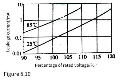
🍍It can be seen that under the conditions of the highest operating temperature and rated voltage, the heat generated by the aluminum electrolytic capacitor will cause the additional temperature rise of the core package of the aluminum electrolytic capacitor by 1~1.5℃, accounting for about 10%~20% of the total temperature rise.
3.3 Temperature characteristics of leakage current
🥝From the qualitative relationship, taking an aluminum electrolytic capacitor with a maximum operating temperature of 85°C as an example, the variation trend of leakage current and temperature is shown in Figure 5.11. It can be seen that the leakage current of aluminum electrolytic capacitors increases significantly with the increase of temperature.

🍅From the quantitative relationship, the relationship between the leakage current of 450V/4700uF, 85℃ aluminum electrolytic capacitors produced by CDE and the ambient temperature is shown in Figure 5.12.
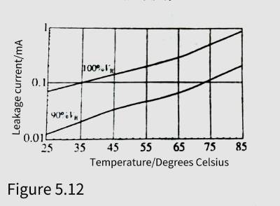
🍆As can be seen from the figure, at the maximum operating temperature of 85°C, the leakage current is 14 times that of room temperature (25°C). The reduction of leakage current can effectively reduce the consumption of electrolyte, which is beneficial to prolong the service life of aluminum electrolytic capacitors.
3.4 Loss of leakage current
🥑As can be seen from Figure 5.10 and Figure 5.12, the leakage current loss of the aluminum electrolytic capacitor at the rated voltage at the highest operating temperature is about 0.4W, while it is only 0.03W at room temperature. If the operating voltage is reduced to 90% rated voltage, the loss can be reduced to 0.004W. It can be seen from the above analysis that proper reduction of the operating voltage and ambient temperature can reduce the leakage current by one to two orders of magnitude, which is extremely beneficial to the long-term and reliable use of aluminum electrolytic capacitors.
🥦Therefore, from the perspective of leakage current, whether aluminum electrolytic capacitors are used or not, it is best to regularly charge and form to ensure the performance of aluminum electrolytic capacitors; aluminum electrolytic capacitors are not suitable for high temperature environments whether they are stored or working, and high temperature environments will greatly The life of the aluminum electrolytic capacitor is shortened, and the leakage current performance of the aluminum electrolytic capacitor is degraded.
4 Relationship between dissipation factor and application of aluminum electrolytic capacitors
🥬Ambient temperature and operating frequency have obvious effects on the loss factor of aluminum electrolytic capacitors. Figure 5.13 shows the relationship between the dissipation factor of aluminum electrolytic capacitors, temperature and frequency.
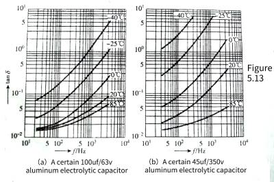
🥒As can be seen from the figure, the loss factor of aluminum electrolytic capacitors will decrease as the temperature rises, so the increase in temperature caused by the loss caused by the loss factor is suppressed, which is a convergence result. Since the resistivity of the electrolyte decreases with increasing temperature, the dissipation factor increases with decreasing predictability (increasing ESR).
🧅The loss factor of aluminum electrolytic capacitors increases with frequency. It can be seen from the figure that when the frequency increases by an order of magnitude, the loss factor approaches an order of magnitude with the increase. This growth is basically consistent with the change trend of tanδ=ωCR in equation (5.13).
🥔It can also be seen from the figure that the actual loss factor increases faster than formula (5.13). The losses generated at different frequencies are different. Therefore, in addition to the loss caused by the ESR, the loss factor of the aluminum electrolytic capacitor also has the loss caused by the electrolyte at different frequencies.
🍡The result of this increase in loss factor with frequency is qualitatively different from the loss factor of non-polar capacitors due to dielectric losses. Because the dielectric (alumina) loss characteristics of aluminum electrolytic capacitors will never be so bad,
5 The relationship between the application environment and life of aluminum electrolytic capacitors
🍧In addition to the application environment affecting the capacitance and leakage current parameters of aluminum electrolytic capacitors, there is another parameter that cannot be seen but has the greatest impact on lead electrolytic capacitors, which is the impact of the application environment on the life of aluminum electrolytic capacitors. Since there are many factors involved in the problem of longevity, this issue will be explained in detail later in this chapter.
6 Influence of Parasitic Parameters of Aluminum Electrolytic Capacitors on Electrical Characteristics
🍨Due to its special structure of aluminum electrolytic capacitors, its parasitic parameters have a great influence on electrical characteristics and need to be carefully studied.
🍭The parameters of aluminum electrolytic capacitors mainly include ESR, parasitic inductance ESL and unidirectional insulation of aluminum oxide dielectric film. The main influences on electrical parameters are the influence of frequency characteristics, the influence of temperature on ESR. and impedance frequency characteristics, the influence of temperature and frequency on loss factor, and the dielectric absorption and residual voltage.
6.1 Equivalent Circuit of Electrolytic Capacitor
🎺Electrolytic capacitors can be represented by different equivalent circuits under different working conditions. The equivalent circuit that can reflect the characteristics of electrolytic capacitors is shown in Figure 5.14.
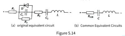
🧬Among them, Figure 5.14(a) is the original equivalent circuit. L and D in the figure are the electrode and lead, respectively.
🔮The resistance of the output terminal, the resistance of the electrolyte, the insulation resistance of the oxide film medium (after damage due to the manufacturing process), the capacitance of the anode foil, the capacitance of the original oxide film of the cathode foil, the inductance caused by the electrode and the lead terminal, and the indication that the anodic oxide film is Diodes with polarity.
🧿Therefore, reverse voltages of electrolytic capacitors in excess of 1.5V will cause large leakage currents, much like diodes conducting forward. In this case, the electrolysis effect will generate hydrogen gas, which will increase the internal pressure and break the pressure release device. At the same time, the reverse voltage will also destroy the alumina dielectric film, so that the withstand voltage of the electrolytic capacitor will drop sharply until it fails. This is the reason why electrolytic capacitors cannot be applied in reverse polarity. The thickness of the original oxide film of the cathode foil is very thin, and there is basically no withstand voltage. And there is little residue under the action of negative voltage. Therefore, the capacitance of the original oxide film of the cathode foil can be regarded as a short circuit.
🎊The equivalent circuit of general application mostly adopts the simplified equivalent circuit, that is, in Figure 5.14(a), combining, ignoring (small leakage current) and D (no reverse voltage applied in normal application), the commonly used equivalent circuit is obtained, As shown in Figure 5.14(b). In Fig. 5.14(b), L and L are not expected to exist in capacitors, but are parasitic parameters of aluminum electrolytic capacitors. The parasitic parameters of aluminum electrolytic capacitors have a great impact on the performance of aluminum electrolytic capacitors.
🎉The following is an analysis of parasitic parameters and effects of aluminum electrolytic capacitors.
6.2 The relationship between the equivalent series resistance of electrolytic capacitors and the application environment
🥂 The resistance of the electrolyte is the main part of the ESR of the aluminum electrolytic capacitor. Moreover, the resistivity of most electrolytes decreases with the increase of temperature, so the ESR of electrolytic capacitors also decreases with the increase of temperature. For example, the relationship between the impedance frequency characteristics and temperature of a 100UF/63 V and 47UF/350 V aluminum electrolytic capacitor is shown in Figure 5.15. The graph shows the impedance frequency characteristics from -40 to +85°C typical temperature.
🍢The lowest value of each curve in the figure can be regarded as the ESR value. It can be seen from the figure that the ESR of the 100UF/63V aluminum electrolytic capacitor is close to 1.5Ω at -40°C, drops to 0.5Ω at -25°C, drops to 0.1Ω at 0°C, and is 0.05Ω at room temperature +25°C. The ESR at the maximum operating temperature of +85℃ is the lowest, which is 0.04Ω; the ESR of the 47UF/350V aluminum electrolytic capacitor is close to 6Ω at -40℃, drops to 3Ω at -25℃, and drops 1.2Ω at 0℃. It is 0.4Ω at +20°C, while the ESR at the maximum operating temperature of +85°C is the lowest, which is 0.06Ω. It can be seen that the ESR decreases by 35%-50% from 25°C to the high temperature limit, but the ESR increases at low temperature It is quite obvious that the ESR increases by about an order of magnitude from 0∽-40°C. If you go from the highest operating temperature to the lowest operating temperature, the ESR increases 50-100 times.
🥪Generally, the ESR of aluminum electrolytic capacitors varies relatively little with frequency, ranging from 0.002Ω for large-capacity screw-terminal aluminum electrolytic capacitors to 20∽30Ω for small-capacity lead-type aluminum electrolytic capacitors.
6.3 Impedance Frequency Characteristics of Electrolytic Capacitors
1 Impedance frequency characteristic analysis
🥟The aluminum electrolytic capacitor obtained from Figure 5.14 is equivalent to the RLC series circuit, from which the impedance frequency characteristics of the aluminum electrolytic capacitor can be obtained, as shown in Figure 5.15.
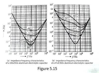
🍰As can be seen from the figure, when the impedance is lower than the resonant frequency, the capacitive reactance of the capacitor is the main impedance. The aluminum electrolytic capacitor with poor frequency characteristics or the aluminum electrolytic capacitor with large capacitance can only maintain to 20 kHz or even lower in this frequency band. Aluminum electrolytic capacitors with good performance or low capacitance aluminum electrolytic capacitors can reach or exceed 100kHz or even higher. In this frequency band, as the frequency increases, the capacitive reactance decreases and the inductive reactance increases. Since the capacitive reactance is the main component, the impedance of the aluminum electrolytic capacitor decreases with the frequency in this frequency band.
🍯As the frequency increases, the capacitive reactance decreases and the inductive reactance increases. When the capacitive reactance is equal to the inductive reactance and cancels each other out, the frequency is the spectral vibration frequency of the aluminum electrolytic capacitor, and the impedance at this time is the lowest. Only the equivalent series resistance remains. (ESR), if the ESR is zero, the impedance at this time is also zero. Because the ESR of aluminum electrolytic capacitors is relatively high. The sum of capacitive reactance and inductive reactance is lower than ESR in a relatively wide frequency band. The impedance frequency characteristics of aluminum electrolytic capacitors are relatively flat in a relatively wide frequency band. At this time, for AC, aluminum electrolytic capacitors are only equivalent to “resistance”. “.
🍹The frequency continues to rise. The inductive reactance begins to be greater than the capacitive reactance. When the inductive reactance is close to the ESR, the impedance frequency characteristic begins to rise and becomes inductive.
🍛A capacitor from this frequency is actually an inductor. Due to the manufacturing process, the larger the capacitance, the larger the parasitic inductance, the lower the resonant frequency (in fact, the increase in the capacitance itself leads to a decrease in the resonant frequency), and the lower the frequency of the capacitor is inductive. This is the reason why some literature and some people often say that “large capacitors filter low frequencies, and small capacitors filter high frequencies” in terms of filtering.
2. Impedance (Z)
🍬The impedance of the aluminum electrolytic capacitor is actually the sum of the capacitive reactance, ESR, and inductive reactance in the equivalent circuit of Figure 5.15. The relationship between impedance Z and capacitive reactance, ESR, and inductive reactance is
![]()
3. Measurement of Z
💧Aluminum electrolytic capacitors, Z are equivalent series circuit tested under a measurement bridge powered by a variable frequency power supply at 25°C, with a tunable AC signal voltage of 1 V rms between 10 Hz ∽ 100 kHz. Impedance measurement is mainly a typical characteristic curve and low temperature limit measurement.
🌸For low temperature impedance measurements. Place the capacitor in a temperature-controlled box, set the low temperature limit ± 2°C, and measure the impedance at 120 ± 5 Hz using any suitable method that provides ± 2.5% accuracy. After the temperature has stabilized, the voltage should be measured with the lowest possible AC as soon as possible so that it does not cause the capacitor to heat up. The capacitor was assumed to be thermally stable by showing no change in two consecutive measurements over a 15 min interval.
4.Z temperature characteristics
🌞As can be seen from Figure 5.15, the temperature characteristics of the capacitive impedance of aluminum electrolytic capacitors and the temperature characteristics of the inductive reactance due to parasitic inductance basically do not change with temperature, and the impedance temperature characteristics only change greatly with temperature when ESR plays a major role. This is determined by the temperature characteristics of the resistivity of the electrolyte.
5. Equivalent series inductance
🎄The inductance is an equivalent series inductance and is relatively independent of frequency and temperature. Typical values range from 2 to 8 nH for SMT, 10-30 nH for radial leads, and 20 nH for axial leads. These inductance values vary with the number of lead-out electrode locations and lead-out methods.
6. Resonant frequency
🌲The resonant frequency is the frequency when the capacitive reactance 1/(2nfC) is equal to the willing reactance 1/(2nfL). This is because the phase difference between the capacitive reactance and the inductive reactance is 180°, the two reactances cancel each other out, and the remaining impedance is pure resistance , equal to the ESR at this frequency. The impedance above the resonance frequency is inductive. For aluminum electrolytic electric appliances, the typical value of the resonance frequency should be much higher than the rectification and filtering frequency of the 120 Hz capacitor. The current resonance frequency of aluminum electrolytic capacitors is generally above 20 kHz. As far as power frequency rectification and filtering are concerned, it is sufficient, and for high-frequency filtering, it can reach resonance frequencies above 100 kHz.
7 Dielectric absorption and residual voltage
🌳Dielectric absorption is generally considered to be a phenomenon in which both ends of a capacitor are short-circuited for a period of time, and then after the short circuit is removed, the terminal voltage of the capacitor gradually rises and finally stabilizes at a certain value. Usually this phenomenon can be called residual voltage. The detrimental effects of this feature in use are mainly two-fold, important for RC timing circuits, trigger systems and phase shift networks. The residual voltage generated by the dielectric absorption of aluminum electrolytic capacitors may reach 10% of the voltage before discharge in 100s~1000s at a temperature of 25 °C. At higher temperatures, the residual voltage will be higher. The voltage may reach 40~50V or even higher. This can lead to accidental discharges, especially the possibility of an electric shock to a person.
🌹The residual voltage generated by the maximum dielectric absorption can be discharged by a short circuit of 1 min by charging at rated voltage for 1h. The next period of time can be measured with a high-resistance potentiometer.
💦Another explanation for the residual voltage of the aluminum electrolytic capacitor is that the anode/cathode aluminum foil is corroded very rough in order to increase the electrode surface area, so that the depth of the rough anode electrode corresponds to the cathode of the electrolyte. The liquid has a high resistivity, so that the capacitance deep in the rough anode electrode to the terminal has actually become an RC circuit. It is impossible for a short-term short circuit to completely discharge the electric charge deep in the rough anode electrode through its parasitic resistance and leave the remaining A considerable part of the charge, when the short circuit is removed, the charge inside the aluminum electrolytic capacitor will be rebalanced, and the final balance result is the residual voltage value. Dielectric absorption and parasitic resistance play a greater role in the process of generating residual voltage. The author believes that parasitic resistance plays a greater role in aluminum electrolytic capacitors, because it is said in university physics that the polarization relaxation time of the dielectric is very short. , even with polar media, the polarization relaxation time is only 0.00001-0.001.
🌊The discharge of aluminum electrolytic capacitors should be through resistance instead of direct short-circuit. For high-voltage and large-capacity aluminum electrolytic capacitors, a bleeder resistor should be connected in parallel to avoid the generation of residual voltage.
7 Thermal Effect of ESR and Thermal Resistance of Aluminum Electrolytic Capacitors
7.1 Thermal Effects of Equivalent Series Resistance (ESR)
⭐️The ripple current flowing through the ESR of the aluminum electrolytic capacitor will generate a power loss of P= and cause the aluminum electrolytic capacitor to heat up.
🌟Compared with power semiconductor devices, the heat dissipation ability of aluminum electrolytic capacitors is very poor. Therefore, the internal temperature of the aluminum electrolytic capacitor will increase significantly with a little power consumption, thereby reducing the service life of the aluminum electrolytic capacitor. Therefore, in addition to knowing the influence of the ESR of aluminum electrolytic capacitors in circuit operation, we should also pay attention to the heat dissipation capability of aluminum electrolytic capacitors, that is, thermal resistance.
7.2 Thermal resistance
✨In large aluminum electrolytic capacitors, a large ripple current usually flows, causing the aluminum electrolytic capacitor to heat up. In order to dissipate the heat generated by the aluminum electrolytic capacitor, the temperature of the aluminum electrolytic capacitor core package will be higher than the temperature of the shell, that is, the aluminum electrolytic capacitor has a temperature rise from the shell to the core package, and this temperature rise is very important. Determines the working state and life of aluminum electrolytic capacitors. If the heat dissipation capability (ie thermal resistance) of the aluminum electrolytic capacitor from the core package to the shell is known, it is easy to calculate whether the temperature of the aluminum electrolytic capacitor core package is within the desired value or design requirements through the measurable ripple current and shell temperature. Inside. The packaging forms of aluminum electrolytic capacitors are mainly divided into three categories; bolt lead-out terminals (large aluminum electrolytic capacitors or high ripple current aluminum electrolytic capacitors), pin-type aluminum electrolytic capacitors (medium aluminum electrolytic capacitors or medium ripple current aluminum electrolytic capacitors), Leaded Aluminum Electrolytic Capacitors and Surface Mount Aluminum Electrolytic Capacitors (Small Aluminum Capacitors or Low Ripple Current Aluminum Electrolytic Capacitors).
🔥The thermal resistance from the case to the environment is basically the same for the same case size and shape of the same manufacturer, but the thermal resistance from the core to the case of the aluminum electrolytic capacitors of different aluminum electrolytic capacitor manufacturers is quite different. The main reason is that the manufacturing process of each manufacturer is different. If the electrolyte only infiltrates the core pack of the aluminum electrolytic capacitor without filling the entire interior of the casing, the gas between the core pack and the casing is a gas with poor thermal conductivity, and the thermal resistance is naturally relatively high. The European aluminum electrolytic capacitor manufacturers that focus on reliability and long life fill the aluminum electrolytic capacitor with electrolyte (that is, the liquid aluminum electrolytic capacitor that is often referred to in China). The value of the ripple current allowed to flow through the aluminum electrolytic capacitor is also greatly increased. Another effective way to reduce the thermal resistance of aluminum electrolytic capacitors from the core package to the shell is to “sit” the negative aluminum foil of the aluminum electrolytic capacitor directly on the shell to increase the thermal conductivity and reduce the thermal resistance from the core package to the shell.
🌈It can be seen from the above analysis that the products produced by different aluminum electrolytic capacitor manufacturers have basically the same thermal resistance from the shell to the environment with the same or similar shape, while the thermal resistance from the core package to the shell is quite different. If only considered from the quality point of view, the thermal resistance from the core package to the case reflects the application quality of the aluminum electrolytic capacitor.
🍄Among the many aluminum electrolytic capacitor manufacturers in the world, very few can give the thermal resistance of the aluminum electrolytic capacitors they produce. Some do not have this data (such as many domestic manufacturers of aluminum electrolytic capacitors), while others need technical confidentiality. Of course, some feel that the thermal resistance of their own aluminum electrolytic capacitors is too large, too shy, and it is harmful to publish them. .
🌼Leaded aluminum electrolytic capacitors are small in size and rated ripple current. Usually, the requirements of designing electronic circuits can be well met without considering thermal resistance.