This article introduces the converter stations with relatively new technology that have been in operation in China. For different DC converter stations, the protection related values and some principles may be slightly different. When reading, readers will not be affected in learning and mastering the basic information such as the overall protection principle and judgment criteria of the AC filter. The following introduces the specific content of large and small AC filter and shunt capacitor device protection.
1 Small group AC filter differential protection
1.1 Purpose and scope of protection
The purpose of this protection is to detect the internal grounding and phase-to-phase short-circuit faults of the AC filter group and the shunt capacitor group.
The protection range is the area between the head end TA and the tail end TA of the AC filter group and the shunt capacitor group. This article introduces a commonly used ratio brake differential protection. The ratio differential protection can reflect the internal phase-to-phase short-circuit fault and ground short-circuit fault of the AC filter, capacitor, and reactor (some protection equipment manufacturers also configure differential current speed cut protection, differential current over-limit protection, etc., and differential current speed cut protection can be used to quickly cut off serious internal faults of the filter). Shunt capacitor device protection can also effectively prevent electrical faults of the shunt capacitor group.
1.2 Protection principle
Measure the current on the high-voltage side and low-voltage side of the filter group and the parallel capacitor group, and compare the differential current phase by phase. The protection is only sensitive to the power frequency. The protection principle is shown in Figure 1.
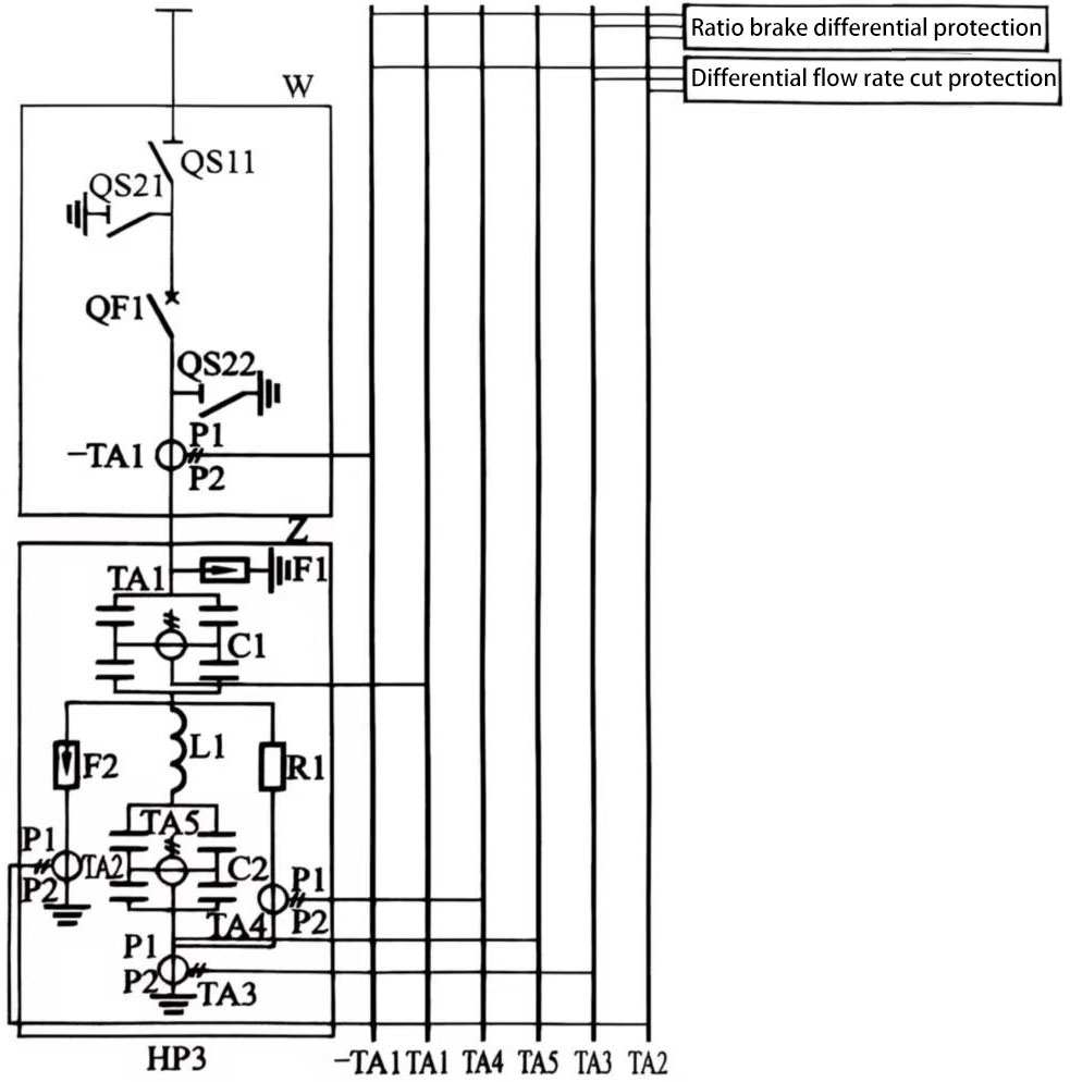
Figure 1 Schematic diagram of differential protection of small group AC filter
1.3 Protection criterion and logic
Calculate the maximum current error and total current error based on the error of TA at the rated current. The differential current setting should avoid the total current error.
The ratio differential action equation is shown in formula (1):
 (1)
(1)
Iop is the differential current, Iop.0 is the differential minimum action current setting value, Ires is the braking current, Ires.0 is the minimum braking current setting value, S is the ratio braking coefficient setting value, and the direction of the current on each side is the positive direction pointing to the filter.
(1) For three-side differential (such as HP3 high-pass filter, lightning arrester grounding current transformer), Iop is as shown in formula (2)
![]() (2)
(2)
The braking current is the grounding current.
İ1, İ2, İ3 are the currents on the secondary side of the current transformers TA1 on the bus side of the filter, TA3 on the grounding side, and TA2 on the lightning arrester side.
(2) For two-side differential (the case where the F2 lightning arrester has no grounding current transformer), Iop is as shown in formula (3):
![]() (3)
(3)
The braking current is the grounding current.
İ1 and İ2 are the currents of the secondary side of the current transformers TA1 on the bus side and TA3 on the ground side of the filter respectively.
The action characteristics of the ratio differential protection are shown in Figure 2.

Figure 2 Ratio differential protection characteristic diagram
The logic of the ratio differential protection is shown in Figure 3.

Figure 3 Ratio differential protection logic diagram
Note: This differential has a delay function, and the specific delay is directly included in the action of the ratio differential element.
1.4 Consequences of protection action
Stage I: Delayed tripping, starting circuit breaker failure protection, and locking the AC circuit breaker.
Stage II: Immediate tripping, starting circuit breaker failure protection, and locking the AC circuit breaker.
2 Group filter capacitor unbalance protection (taking ratio unbalance as an example)
2.1 Purpose and scope of protection
The purpose of this protection is to protect the high-voltage end capacitor of the H-bridge structure to avoid capacitor avalanche damage due to component failure.
The protection range is the entire H-bridge arm capacitor.
2.2 Protection principle and strategy
(1) Capacitor count unbalance protection
(2) Capacitor ratio unbalance protection (the most basic configuration of the converter station, some converter stations are equipped with capacitor bridge arm current imbalance protection).
(3) Capacitor bridge differential overcurrent protection.
If the fuse of a capacitor unit is blown, the capacitance of the bridge arm changes, resulting in an unbalanced current flowing through the bridge. The increase of the unbalanced current is detected and the protection is activated. The protection principle is shown in Figure 4.

Figure 4 Schematic diagram of group filter unbalance protection
Due to the manufacturing deviation of the capacitor, the total current of the filter is needed to balance the initial unbalanced current. The current correction is only performed when the filter is charged for the first time or after the capacitor is replaced. Protection coordination: The selection of protection settings should avoid capacitor avalanche damage. The protection of the Shunt capacitor device protection that the capacitor group responds in time to an unbalanced fault and avoids equipment damage due to current imbalance.
2.3 Protection criteria and setting principles
Usually, there are three levels of protection in the converter station: alarm, delayed tripping and immediate tripping.
(1) Alarm. It can maintain operation for at least 2 weeks without damaging the equipment and affecting the system.
(2) Delayed tripping. Delayed tripping for 2 hours.
(3) Tripping. Immediate tripping.
2.4 Protection action sequence
(1) Alarm.
(2) Tripping stage I. Delayed tripping, breaker failure protection started, AC circuit breaker locked.
(3) Tripping stage II. Immediate tripping, breaker failure protection started, AC circuit breaker locked.
3 Group filter resistance circuit/reactance circuit harmonic overload protection
3.1 Purpose and scope of protection
The purpose of this protection is to protect the reactor or resistor from thermal damage.
The protection scope is the resistor and reactor in the filter, and the protection of the shunt capacitor device protection is also included that these devices are not damaged by overload during operation.
3.2 Protection principle and strategy
The protection calculates the power loss of each component and integrates the power loss according to the thermal time constant of the component to determine the thermal stress on the component. The protection simulates the skin effect of the reactance and corrects the power loss. If the calculated temperature value exceeds the thermal rating of the component, the protection is activated and the AC circuit breaker is tripped. The principle is shown in Figure 5.

Figure 5 Schematic diagram of harmonic overload of resistors/reactors
Generally, capacitors can withstand 1.3 times the rated current. This protection is used to prevent damage to the capacitor caused by heating when the current is higher than this. The protection of Shunt capacitor device protection that when the current is overloaded, the capacitor and other related devices are protected in time to prevent damage to the equipment caused by heating. The purpose of its protection is to eliminate thermal overload faults, not short-circuit faults. The alarm of stage I has delayed tripping, and stage II has delayed tripping.
3.3 Protection judgment criteria and setting principles
The selection of protection settings should avoid component damage.
3.4 Protection action sequence
(1) Alarm.
(2) Trip stage I. Delay tripping, start circuit breaker failure protection, and lock the AC circuit breaker.
(3) Trip stage II. Immediate tripping, start circuit breaker failure protection, and lock the AC circuit breaker.
4 Small group filter overcurrent protection and shunt capacitor device protection
4.1 Purpose of protection
The purpose of this protection is to protect the filter group or parallel capacitor group to prevent damage caused by overcurrent.
4.2 Protection principle and strategy
Measure the current on the filter group or parallel capacitor group. The protection is only sensitive to the power frequency. Protect the filter group, capacitor group, and reactor group to prevent damage caused by overcurrent. The action formula is: I > Iset; where I is the secondary current of TA on the high-voltage side, and Iset is the set value. The protection can be set to multiple setting values as needed, which can act on alarm and tripping respectively. Alarm in stage I, delayed tripping in stages II and III.
4.3 Protection judgment and setting principle
(1) Alarm. The setting of the alarm level ensures that it will not be activated when the system voltage fluctuates normally. The typical value of the alarm level is 1.1 (per unit value).
(2) Delayed tripping. Delayed tripping at 1.3 times the rated load current, the typical value of the delay is equal to 1.5s.
(3) Immediate tripping. This part is used as a backup protection for differential protection. The trip level is higher than the highest current (inrush current) that may occur in the filter group, but lower than the lowest short-circuit current level. The protection of the shunt capacitor device protection will be adjusted according to the specific situation to avoid damage.
4.4 Protection action sequence
(1) Alarm.
(2) Section I. Delayed tripping, starting circuit breaker failure protection, locking the AC circuit breaker.
(3) Section II. Immediate tripping, starting circuit breaker failure protection, locking the AC circuit breaker.
5 Zero-sequence current protection of small group filters and shunt capacitor device protection
5.1 Purpose and scope of protection
The purpose of this protection is to protect the AC filter from short-circuit faults. The most important thing is to detect faults at the low-voltage end, because the fault current is small and the differential protection may not detect it. This protection also detects open-circuit faults in each phase, such as unsuccessful tripping or closing of a single phase.
5.2 Protection principle and strategy
Measure the three-phase currents at the low-voltage end of the filter and add them to obtain the zero-sequence current. In order to reduce the impact of the difference between the 11th and 13th harmonics, the protection is only sensitive to the power frequency and has a time-limited characteristic.
5.3 Protection criteria and setting principles
(1) Alarm. The current setting is higher than the normal unbalanced current (3I0) and the zero-sequence current caused by the measurement error. The typical value is 15% of the power frequency load current.
(2) Delay tripping. ① The typical value of the delay is equal to 10s. According to the zero-sequence current caused by the internal fault of the filter, this protection is used to detect faults that are difficult to detect by the differential protection. The setting value is as low as possible. However, the tripping level is higher than the normal unbalanced current (3I0) and the zero-sequence current caused by the measurement error. A reasonable choice is 20% of the rated power frequency load current. ② The typical value of the delay is equal to 4s. The delay can avoid out-of-zone faults and protection malfunctions. The shunt capacitor device protection must also ensure that the normal operation of the equipment will not be affected when a fault current occurs.
5.4 Protection action sequence
(1) Alarm.
(2) Tripping. Start the circuit breaker failure protection and lock the AC circuit breaker.
6 Group filter detuning monitoring protection and shunt capacitor device protection
6.1 Purpose and scope of protection
The purpose of this protection is to detect small changes in the early values of the filter components.
The protection scope is the group AC filter.
6.2 Protection principle and strategy
The TA at the low-voltage end of each filter detects the zero-sequence harmonic current and obtains the zero-sequence current through the vector sum of the three-phase current. The protection is sensitive to harmonic zero sequence and detects the change of the single-phase impedance of the filter. If one phase is detuned, the harmonic cannot pass through the filter, and at the same time, it causes overstress to the normal filter due to asymmetry. The detuning monitoring function cannot distinguish whether the zero-sequence harmonic component is caused by a filter fault or an AC system fault.
6.3 Protection judgment criteria and setting principles
The total harmonic current is calculated based on the total rated current and rated power frequency current during continuous operation. The judgment criteria should ensure that even if there is no maximum harmonic component in normal operation, an alarm should be issued once the detuning occurs. The total harmonic current is calculated as shown in formula (4):
![]() (4)
(4)
Where It-total rated current, A;
If-rated power frequency current, A;
Iht-total harmonic current, A.
The typical value of zero-sequence current is set to 35% of the total harmonic current, with a delay of 2min. The shunt capacitor device protection works together in this process to ensure that the capacitor will not suffer unnecessary damage due to detuning.
6.4 Protection action results
Alarm.