1.Aging of insulating media and causes of capacitor damage
(1) Aging of liquid dielectric insulation. The main manifestations of aging: increased loss, usually accompanied by an increase in trace moisture, the appearance of macromolecules and small molecules, gas precipitation (causing capacitor bulging), etc. Causes of insulating oil aging: mainly due to the chemical action of free radicals and the catalytic action of impurity ions. These factors are one of the causes of capacitor damage and directly affect its service life and performance.
The production process of oil is a reversible chemical reaction process, and it is difficult to avoid the existence of free radicals in insulating oil. Free radicals are atomic groups with lone electrons and have great chemical activity. Modern science has confirmed that many chemical reactions are completed with the help of the activity of free radicals. Under certain conditions, free radicals will react chemically with the unsaturated bonds on the benzene ring, resulting in an increase in molecular weight and the appearance of macromolecules, which may be accompanied by an increase in the viscosity of the liquid medium. Condensation reactions may also occur between free radicals, which also results in the production of macromolecules, but the micro-water content of the oil sample will increase. Free radicals may also cause oil molecules to crack and produce small molecules. The chemical reaction of free radicals causes the performance of the oil to deteriorate, which results in the aging of the insulating oil and is one of the causes of capacitor damage
(2) Aging of solid dielectric (polypropylene film). The main manifestation of aging is a decrease in breakdown voltage, not an increase in loss. Because the small molecules produced by film aging will dissolve in the oil, they will not affect the loss of the film, and the deorientation of the film will not significantly increase the loss. The main cause of aging is similar to that of oil, mainly caused by the chemical action of free radicals and the catalytic action of impurity ions.
The increase in the temperature of the capacitor during operation increases the activity of free radicals and the catalytic action of impurity ions, which accelerates the aging of the polypropylene film. Studies have shown that when the temperature exceeds a certain value, the polypropylene film will deorientate. After biaxial stretching, the polypropylene molecules of electrical polypropylene film have a certain degree of regularity and the film has sufficient dielectric strength. This is the fundamental difference between it and general packaging film. Deorientation means that the electrical film returns to the characteristics of packaging film, and its dielectric strength becomes very low. For filters and parallel capacitor devices in high-voltage DC transmission systems, the harmonic content is large during operation, and the local thermal effect is greater than that of capacitors in other occasions, and the aging problem of the film is relatively prominent. If other impurities are mixed into the polypropylene film during the production or rolling process, it will lead to more frequent breakdown of the capacitor film during operation. When this effect accumulates to a certain extent, the filter or capacitor unbalance protection will trip. As shown in Figure 1, a polypropylene film of a capacitor element inside the capacitor is broken down during the operation of the equipment or at the moment of circuit breaker closing.
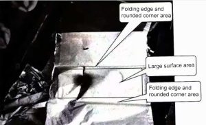
Figure 1 A broken-down capacitor element (located on the large surface of the element)
(3) Methods to solve the problem of insulation aging. In solving the problem of equipment insulation aging, equipment manufacturers should play a more active role. During the factory supervision of the equipment manufacturing stage, the operation and maintenance unit should pay attention to tracking whether the manufacturing links of the equipment manufacturer have achieved the following points.
Is the cleanliness control of the production process strict: Controlling the cleanliness is an effective way to reduce the entry of impurity particles into the capacitor, which can not only reduce the loss of the capacitor, but also reduce the impact of heat in the capacitor. It can also slow down the aging of insulation, especially the aging process of the film, thereby avoiding one of the causes of capacitor damage.
Whether to use oil with high aromaticity: Choosing oil with high aromaticity can not only reduce the electric field strength on the oil layer and delay the aging process of the oil, but also absorb free radicals in the oil and inhibit the growth of the number of free radicals.
Whether to use additive technology: The additive should be a polar mesh medium, which is polarized and carries a strong polarization charge under the action of the electric field. With the mesh structure, it can easily absorb free radicals and inhibit the activity of free radicals.
Whether to use a reasonable structure: A reasonable structure, coupled with an optimized structural parameter design, can reduce the internal temperature rise of the capacitor. The reduction in capacitor temperature during operation means a reduction in free radical activity, which weakens the catalytic effect of impurity ions, thereby delaying the insulation aging inside the capacitor.
2.Internal fuse performance issues causes of capacitor damage
Compared with capacitors used in other occasions, capacitors used in high-voltage DC converter stations have higher performance requirements in all aspects, which is also the reason why capacitors used in converter stations are more easily damaged during operation.
(1) The capacitor has high requirements for surge current impact resistance. The tuning frequency of the capacitor bank for HVDC transmission is high, and the series reactance rate is small, so the surge current multiple is large when switching. In addition, the short-circuit discharge voltage of capacitors for HVDC transmission is relatively high, basically around 2.8 times, 12% higher than the 2.5 times specified in the standard, and the discharge energy is 25% greater.
(2) The steady-state overcurrent capacity of the capacitor is required to be relatively large. The harmonic content of the HVDC system is large, and the current of the capacitor is even greater. For example, the shunt capacitor of the Xingren Converter Station of the Southern Power Grid has a single-phase rated capacity of 94Mvar and a rated voltage of 430kV. The rated current calculated based on the rated capacity and rated voltage is 218A, and the actual rated current is 254A, a difference of 16.5%. The heating of the internal fuse increases by 35.4% during normal operation.
(3) The rated voltage selection of capacitors is different from that of ordinary shunt capacitors. When the harmonic content is large enough, the rated voltage of the capacitor is determined by the rated capacity.
When the harmonic content is small, the rated voltage of the AC capacitor for HVDC is determined by the arithmetic sum of the fundamental and harmonic voltages. The energy storage of the capacitor element during operation is smaller than that during the standard test. Therefore, if the internal fuse is selected according to the current standard, even if the test is passed, the internal fuse may not operate reliably at the lower limit voltage or operate too much at the upper limit voltage during operation. This makes the selection of the internal fuse performance range too narrow, which can easily lead to inappropriate selection of the internal fuse, thus becoming one of the causes of capacitor damage.
(4) The consequences of incorrect internal fuse operation. Each capacitor element in a single capacitor is connected in series with an internal fuse, as shown in Figure 2. The figure shows the internal structure of a capacitor currently used in a domestic converter station. The capacitor adopts a 15-parallel-4-series component connection method. The purpose of setting an internal fuse for each small element is that when the internal capacitor element breaks down, the internal fuse should operate reliably and melt, isolating the faulty capacitor element, while the other elements operate normally. Since only one element inside the capacitor is damaged, the overall capacitance value is not greatly affected, and the overall capacitance value is slightly smaller.
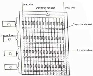
Figure 2 Capacitor internal cross-section
![]() (1)
(1)
(where n is 1, 2, 3, 4)
When the internal components of the capacitor fail due to internal or external reasons, the internal fuse will not work properly (referring to unreliable melting) and will not work properly, which will lead to two opposite results in the external capacitance of the capacitor, as shown in formula (1). Assume that the dielectric of a capacitor element in C4 is broken down, and the internal fuse used to protect the capacitor element is not disconnected. The element is equivalent to a wire that short-circuits the other 14 elements in the entire C4 parallel string. The capacitance value of the entire capacitor Ctotal is obtained by formula (2):
![]() (2)
(2)
When the other parallel string elements are intact, Ctotal will be 4/3 times the original capacitance value, which is larger than the normal rated value. If it is greater than 33% of the rated value, it is an unqualified capacitor. Q/GDW 496-2010 “High Voltage DC Transmission AC/DC Filter and Shunt Capacitor Device Maintenance Specification” stipulates that the difference between the initial value of the filter (assuming the initial value is the rated value) is required to be -5%~+10% to be qualified.
When the internal fuse operates correctly, the result should be smaller. Assume that a capacitor element in C4 is broken down, the internal fuse operates correctly, the branch of the capacitor element is disconnected, and the other elements in C4 work normally. The capacitance Ctotal of the entire capacitor is obtained by formula (3):
![]() (3)
(3)
When other parallel series elements are intact, Ctotal will be 56/57 (98.25%) of the original capacitance value, which is slightly smaller than the normal rated value. If the deviation of capacitor design and manufacturing is considered, when one capacitor element is broken down and the internal fuse operates correctly, it can be considered as a fully qualified capacitor. When two capacitor elements are broken down and the internal fuse operates correctly, it is concluded that Ctotal will be 52/54 (96.3%) of the original capacitance value, and the initial value difference is -3.7%, which is still a qualified product. When three capacitor elements are broken down and the circuit is disconnected, the capacitor will be 94.1% of the rated value, and the initial value difference is -5.9%, which is an unqualified product. Therefore, for a capacitor with a structure of 15 parallel and 4 series, no more than 3 internal fuses should be blown, and the internal fuse should not be blown incorrectly due to the breakdown of the capacitor element. As shown in Figure 3, the left side shows a large surface of the capacitor element being broken down and short-circuited, and the internal fuse not operating correctly, and the right side shows a normal internal fuse blowing.
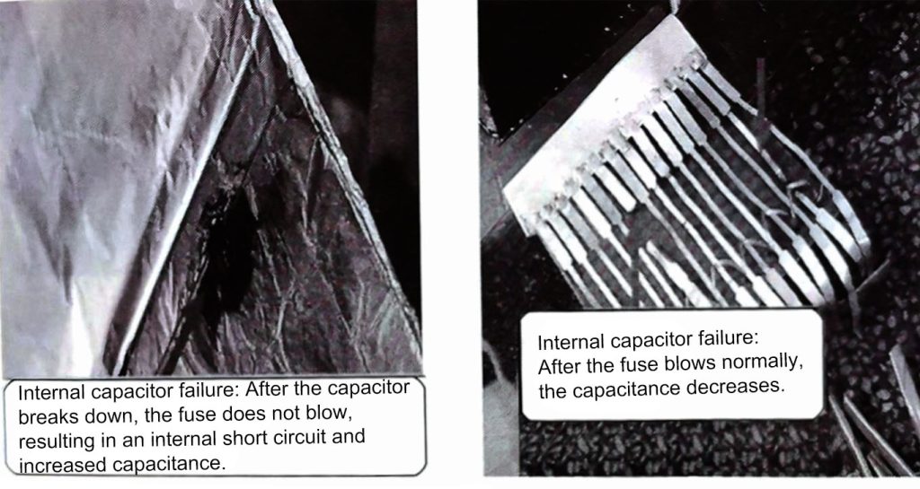
Figure 3 Diagram of the breakdown of internal components of the capacitor and the blowing of the internal fuse
For metal-cased capacitors, the capacitance of the capacitor is affected by temperature and even by the influence of insulating oil (the capacitor with oil leakage is basically unchanged compared with the capacitor without oil leakage). The state of the internal series and parallel components affects the capacitance of capacitors and capacitor banks. For ordinary metal-cased capacitors with this series and parallel connection mode, the breakdown and short circuit of the components are the fundamental reasons for the change in the capacitance of the external capacitor, and are also one of the causes of capacitor damage.
From the above analysis, it can be seen that as a converter station operation and maintenance personnel, the internal structures of various capacitors in the converter station should be clearly understood from the manufacturer during the equipment tracking and installation stage, so as to facilitate the analysis of the internal fault conditions of the capacitor in future work.
3.Joint heating
The problem of temperature rise caused by joint heating is mainly caused by the unreasonable connection structure of capacitor joints. In the early days, some domestic capacitor manufacturers had some defects in joint design. However, as a large number of high-voltage DC transmission capacitors in my country were put into operation, equipment manufacturers are also actively improving joint design technology. In recent years, the problem of heating of capacitor joints caused by unreasonable design has been basically eliminated. However, this is also one of the causes of capacitor damage.
The common practice of equipment manufacturers to solve the problem of joint heating is to use threaded wire clamps and spring washers, as shown in Figures 4 and 5. The focus of the wire clamp plus thread is to solve the problem of current flow channel, so that the current conduction surface of the wire clamp and the wire is the largest and the contact resistance is the smallest. The spring washer can perform temperature compensation to ensure that the contact pressure of each conductive contact surface does not change with the ambient temperature. It is an effective way to control the heating of the joint. Figure 6 shows a schematic comparison of different joint forms of capacitors, and Figure 7 shows an infrared spectrum of the joint heating measured by infrared temperature measurement during operation.
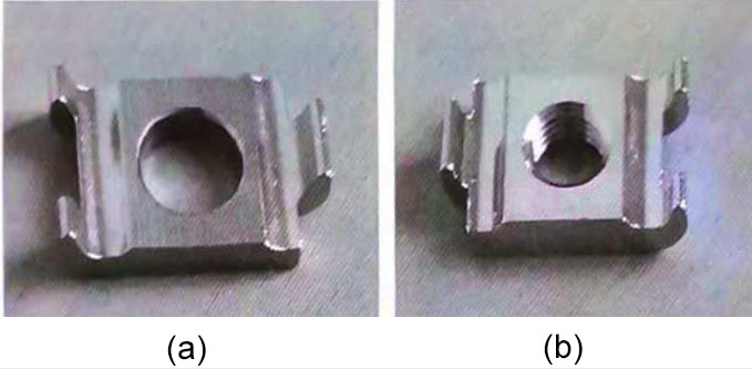
Figure 4 Comparison of old and new capacitor clamps (a) Clamp without internal thread; (b) Clamp with internal thread
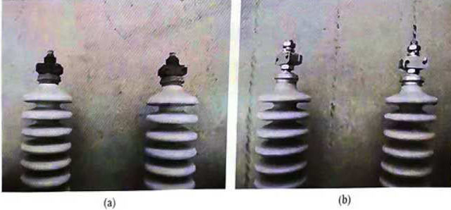
Figure 5 Comparison of capacitor joints with spring washers and without spring washers (a) No spring washers at the joint connection; (b) With spring washers at the joint connection
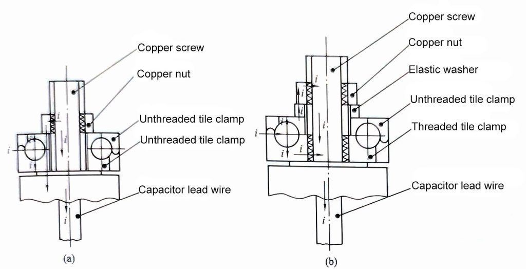
Figure 6 Comparison of schematic diagrams of different capacitor joint forms (a) Wiring method of non-elastic washers and non-threaded tile-shaped clamps; (b) Wiring method of elastic washers and threaded tile-shaped clamps
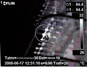
Figure 7 Infrared spectrum of heating conditions of capacitor joints
4.Oil leakage
Oil leakage at the capacitor joint or at the root of the capacitor casing is another typical fault defect of capacitors during operation. Taking the first half of 2009 as an example, the converter stations under the jurisdiction of State Grid Corporation of China (Echeng Converter Station, Lingbao Converter Station, Yidu Converter Station, Huaxin Converter Station, Gaoling Converter Station) had a total of 244 capacitor defects of various types, of which 59 were oil leakage defects, accounting for 24.2% of the total fault defects. The oil leakage defect of capacitors is a long-standing problem for equipment operation and maintenance units and even the entire capacitor industry. There are many reasons for the oil leakage of capacitors during operation, mainly the inadequacy of product manufacturing process and the incorrect methods during installation, construction and transportation. The former mainly relies on the equipment manufacturer to improve the process, and the latter requires the construction unit or operation and maintenance personnel to master the correct construction or maintenance installation process.
Defects in the equipment manufacturing process can lead to oil leakage, which is also one of the causes of capacitor damage. As shown in Figure 8, the traditional outlet bushing. The traditional capacitor porcelain bushing outlet bushing is prone to oil leakage at the joint, as shown in Figure 10; the improved heat-resistant and leak-proof outlet bushing is used, as shown in Figure 9. The bushing and the capacitor shell are soldered with a flange. In addition, the early domestic capacitor products did not install positioning washers, and only relied on nuts to tighten. The change in the temperature of the contact will easily cause the nut to loosen, resulting in heating of the contact. Overheating positions can easily cause the end solder to melt and leak oil. As shown in Figures 9 and 11, the improved blind hole terminal and the rolled sealed sleeve are shown. The one-piece crimped sleeve combines the cover and the sleeve into one without any welds, which improves the sealing reliability. At the same time, during processing, the shell and the bottom, the bottom and the cover are welded by CNC argon arc machine, with small errors and precise positioning, ensuring the high consistency of the welds, further reducing the possibility of product leakage.
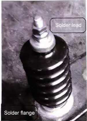
Figure 8 Traditional outlet sleeve
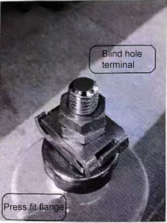
Figure 9 Heat-resistant and leak-proof outlet sleeve
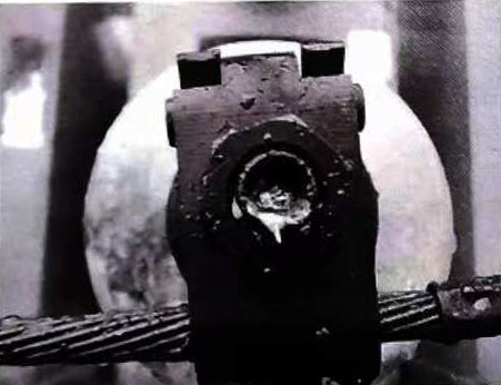
Figure 10 Solder melt causes oil leakage in the joint
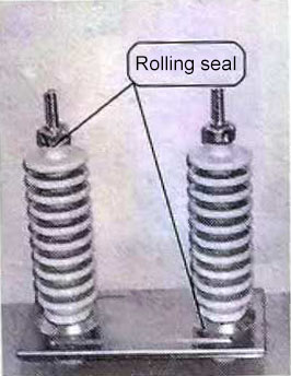
Figure 11 Rolled sealed sleeve
Improper installation or handling methods lead to oil leakage, which is also one of the causes of capacitor damage. Directly lifting the porcelain sleeve during transportation causes the flange welding to lose silver and cracks to appear; excessive force on the nut during wiring causes the porcelain sleeve to lose silver; the paint layer at the shell welding falls off and the shell is corroded. In order to avoid invisible oil leakage defects caused by installation or transportation, on-site operation and maintenance personnel should master the correct methods: when transporting and transferring capacitors, it is strictly forbidden to move the porcelain sleeve, do not tighten the nuts with force, and tighten them according to the torque requirements; when the paint layer falls off, remove rust and repaint in time. In view of this, during the infrastructure installation or maintenance stage, the operation and maintenance personnel should focus on strengthening the supervision and inspection of the construction process on site, and supervise the on-site personnel to use the correct construction methods and methods to complete the maintenance and installation of the capacitors.
[/fusion_text][/fusion_builder_column][/fusion_builder_row][/fusion_builder_container]
